51
PowerScout HD
Communication & Verification
COMMUNICATION & VERIFICATION - DETAILS
This section is intended to support the commissioning of the PSHD meter by an
instrumentation technician. In many cases, the electrical installation is conducted
ahead of the availability of the RTU or was performed by a different installer. Often
the technician is working in concert with a remote programmer who is confirming
the connectivity with a remote host system. A Digital Multimeter (DMM) can be
used to confirm measurements at the board terminals, if necessary.
Once the meter is powered from line voltage, ONLY TOUCH WITH THE
METER IF THE TOUCHSĀF™ HIGH VOLTAGE
COVER IS INSTALLED. For
-circuit meters, it is safe to touch the meter (including the user
buttons) with the top cover remov
ed ONLY if the TouchSāf™ high
ed. Note: The PS12HD-P-D-N (mounting plate
configuration) DOES NOT have a TouchS
āf High Voltage Cover and
should not be touched while powered from line voltage.
Communications settings and real-time data values can be confirmed quickly using the LCD
in
terface if equipped. When significant setup modifications are anticipated, a computer
interface is recommended.
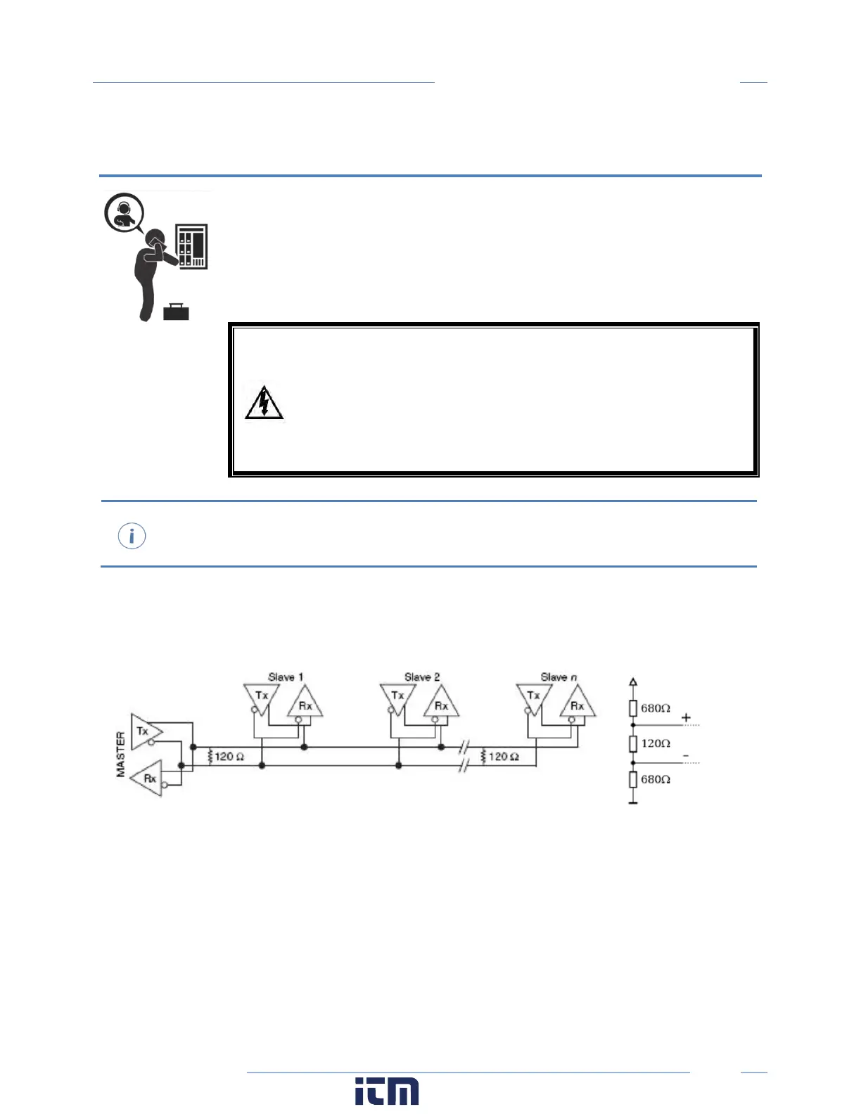
Physical Connections on an RS-485 Multidrop Network
The PSHD meter uses a 2-Wire Half Duplex RS-485 Implementation.
2-Wire Multidrop Network using Terminating Resistors
Termination Resistors—are NOT included on the PSHD meter. If the PSHD meter is at the end of
a daisy-chain, then connect a 120-ohm leaded resistor between the + and – terminal at the
connector.
Bias Resistors—are NOT included on the PSHD meter. Bias resistors are needed if the idle
conditions of the bus are in an indeterminant logic voltage. Bias resistors are usually located at
the master node and are usually 680 ohms for a RS-485 network.
Network Topology—RS-485 is designed to be implemented as a daisy chain (series connections)
rather than star or cascade topologies.
w ww. . com
information@itm.com1.800.561.8187
 Loading...