DigitAx User Guide
Issue code: dgxu4
5-15
5.11 Signal connections
Note
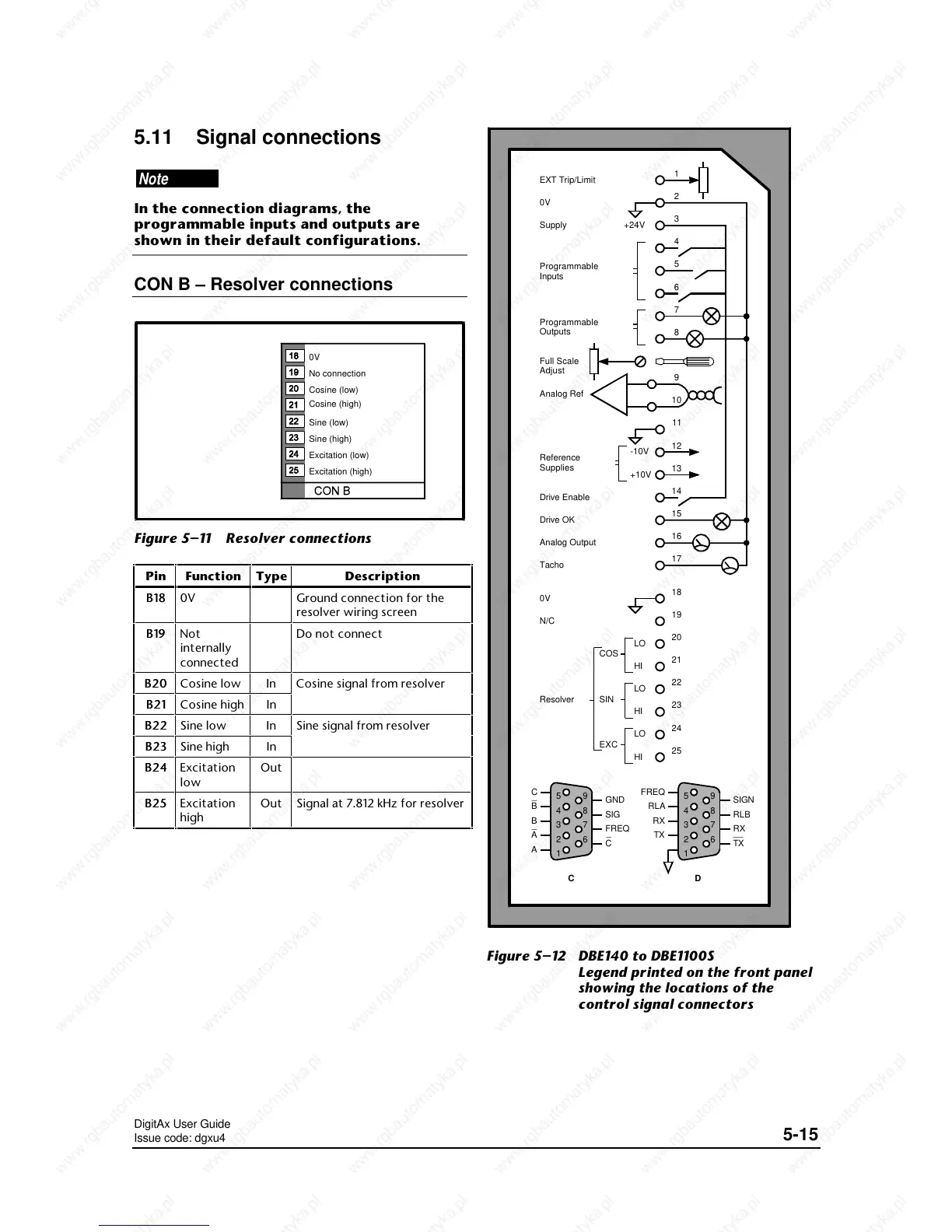
In the connection diagrams, the
programmable inputs and outputs are
shown in their default configurations.
CON B – Resolver connections
No connection
Cosine (low)
Cosine (high)
Sine (low)
Sine (high)
Excitation (low)
Excitation (high)
0V
Figure 5–11 Resolver connections
Pin Function Type Description
B18B18 0V Ground connection for the
resolver wiring screen
B19B19 Not
internally
connected
Do not connect
B20B20 Cosine low In Cosine signal from resolver
B21B21 Cosine high In
B22B22 Sine low In Sine signal from resolver
B23B23 Sine high In
B24B24 Excitation
low
Out
B25B25 Excitation
high
Out Signal at 7.812 kHz for resolver
18
19
20
21
22
23
24
25
1
2
3
6
7
8
9
10
11
12
13
14
15
16
17
4
5
EXT Trip/Limit
0V
Supply
Programmable
Inputs
Programmable
Outputs
Full Scale
Adjust
Analog Ref
Reference
Supplies
Drive Enable
Drive OK
Analog Output
Tacho
0V
N/C
+24V
-10V
+10V
LO
HI
LO
HI
LO
HI
SIN
EXC
COS
Resolver
5
4
3
2
1
9
8
7
6
FREQ
RLA
SIGN
RLB
RX
TX
RX
TX
__
D
SIG
5
4
3
2
1
9
8
7
6
C
B
B
A
A
GND
FREQ
C
_
_
_
C
Figure 5–12 DBE140 to DBE1100S
Legend printed on the front panel
showing the locations of the
control signal connectors
 Loading...