DigitAx User Guide
Issue code: dgxu4
10-3
Pr80 — I
2
t protection
The effect of the values of Pr42 and Pr45 on the
operation of the Drive are important. When the
motor current exceeds the value of I
nom,
(Pr45) the
Drive will start integrating the current with respect
to time constant in Pr55. This integrated value is
displayed in Pr80. The Drive limits the current
when Pr80 reaches 100%. The Drive does not tripdoes not trip
when this point is reached. The display shows It,
and the current is limited the to the level set in
Pr45.
When the motor current reduces to below the value
set in Pr45, the integrator starts to count down
towards 0. This allows for short periods of high
over-load to be tolerated, particularly during
acceleration and deceleration cycles.
Current in excess of 110% of I
pk
(which would
indicate an abnormal condition such as a short-
circuit or a ground fault in the motor circuit)
activates a hardware trip circuit. This produces
over-current trip OC, and discontinues the current
in the motor.
Analysis of the effective current
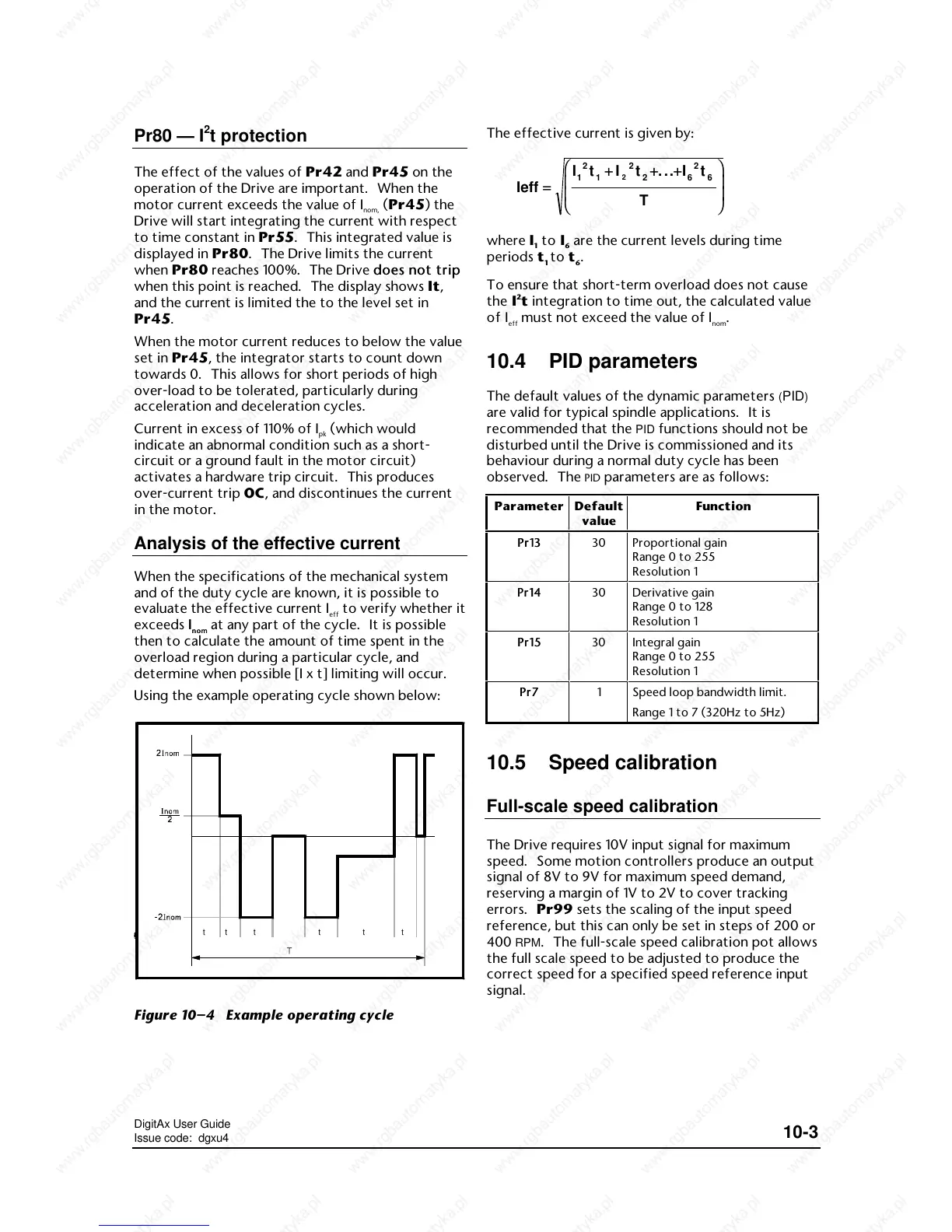
When the specifications of the mechanical system
and of the duty cycle are known, it is possible to
evaluate the effective current I
eff
to verify whether it
exceeds II
nomnom
at any part of the cycle. It is possible
then to calculate the amount of time spent in the
overload region during a particular cycle, and
determine when possible [I x t] limiting will occur.
Using the example operating cycle shown below:
t
1
t
2
t
3
t
4
t
5
t
6
Figure 10–4 Example operating cycle
The effective current is given by:
Ieff
It I t ...It
T
1
2
1
2
26
2
6
2
==
++++++
where I
1
to I
6
are the current levels during time
periods t
1
to t
6
.
To ensure that short-term overload does not cause
the I
2
t integration to time out, the calculated value
of I
eff
must not exceed the value of I
nom
.
10.4 PID parameters
The default values of the dynamic parameters (PID)
are valid for typical spindle applications. It is
recommended that the
PID functions should not be
disturbed until the Drive is commissioned and its
behaviour during a normal duty cycle has been
observed. The
PID parameters are as follows:
Parameter Default
value
Function
Pr13Pr13 30 Proportional gain
Range 0 to 255
Resolution 1
Pr14Pr14 30 Derivative gain
Range 0 to 128
Resolution 1
Pr15Pr15 30 Integral gain
Range 0 to 255
Resolution 1
Pr7Pr7 1 Speed loop bandwidth limit.
Range 1 to 7 (320Hz to 5Hz)
10.5 Speed calibration
Full-scale speed calibration
The Drive requires 10V input signal for maximum
speed. Some motion controllers produce an output
signal of 8V to 9V for maximum speed demand,
reserving a margin of 1V to 2V to cover tracking
errors. Pr99 sets the scaling of the input speed
reference, but this can only be set in steps of 200 or
400
RPM. The full-scale speed calibration pot allows
the full scale speed to be adjusted to produce the
correct speed for a specified speed reference input
signal.
 Loading...