DigitAx User Guide
Issue code: dgxu4
10-10
Use the following procedure to select Stop-and-hold
mode:
1. Configure terminal B6 as follows for the
voltage sense of the Stop signal:
b88 setting Stop signal
0 +24V
10V
2. Set b22 at 1 for stopping with ramps.
3. Set Pr11 and Pr12 for deceleration rate in
milliseconds per 1000
RPM.
Limit-switch stop-and-hold
When a limit-switch is triggered, the Drive inhibits
rotation in that direction, and stops the motor. The
motor can be stopped without deceleration ramp
(stopping under current limit), or ramps can be
included to make the stop smoother. When the
motor has stopped, the Drive will keep the motor in
torque to prevent the mechanical system from
moving past the end-stop.
Ramps are selected by setting b23 at 1. When the
limit-switch is activated, the Drive decelerates the
motor at the rate set in Pr11 or Pr12. Selection of
ramps for the limit-switch stop-and-hold mode is
independent of whether or not ramps are selected
to act on the speed reference.
Use the following proceudre to configure the limit-
switch stop functions:
1. Set b16 at 1.
2. Set b23 at 1 to select ramps.
3. Apply the limit-switch signals as follows:
Limit-
switch
Terminal
B4 B5
Forward X 0
Reverse 0 X
0 = logic 0 = 0V = Stop
(X = don’t care)
Stop, hold and orientate
See Spindle orientation earlier in this chapter.
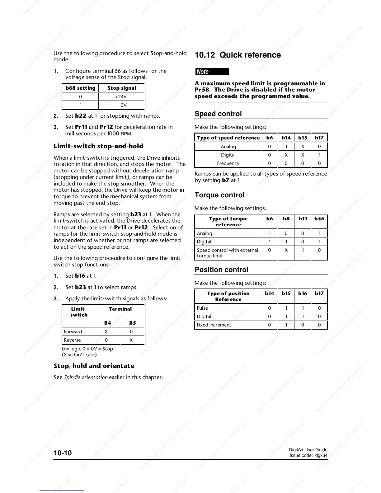
10.12 Quick reference
Note
A maximum speed limit is programmable in
Pr58. The Drive is disabled if the motor
speed exceeds the programmed value.
Speed control
Make the following settings:
Type of speed reference
 Loading...