DigitAx User Guide
Issue code: dgxu4
13-1
13 Serial Communications
13.1 Introduction
Serial communications can be used by a host
computer or PLC to read and edit parameters, and
control any function on the Drive. The serial
communications port is an RS422/RS485
specification, and allows the host to communicate
with up to 32 Drives on a single line. The protocol is
industry standard ANSI x 3.28–2.5–A4
13.2 Connecting the Drive
RS485 and RS422
RS485 uses 4-wire differential lines which ensure a
high level of immunity to noise. It also has high
common-mode rejection.
RS485 full-duplex four-wire connection allows
multi-drop links to be made to a maximum of 32
Drives. See Figure 13–1. The maximum permissible
cable length for each link is 1200m (3700 feet).
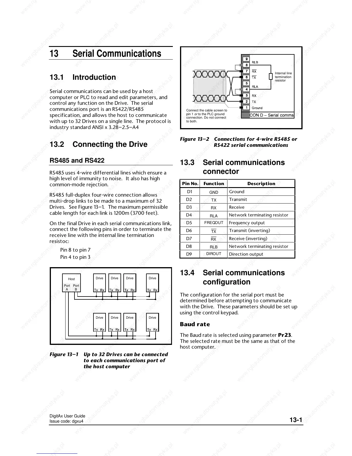
On the final Drive in each serial communications link,
connect the following pins in order to terminate the
receive line with the internal line termination
resistoc:
Pin 8 to pin 7
Pin 4 to pin 3
DriveDriveDriveDrive
DriveDriveDriveDrive
Host
Port
A
Port
B
Figure 13–1 Up to 32 Drives can be connected
to each communications port of
the host computer
Connect the cable screen to
pin 1
or
to the PLC ground
connection. Do not connect
to both.
Internal line
termination
resistor
Figure 13–2 Connections for 4-wire RS485 or
RS422 serial communications
13.3 Serial communications
connector
Pin No. Function
13.4 Serial communications
configuration
The configuration for the serial port must be
determined before attempting to communicate
with the Drive. These parameters should be set up
using the control keypad.
Baud rate
The Baud rate is selected using parameter Pr23.
The selected rate must be the same as that of the
host computer.
 Loading...