User Manual
35
/
76
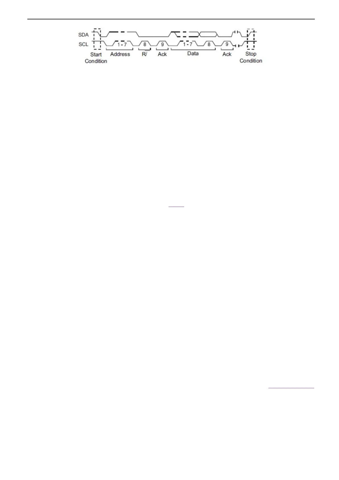
Start: trigger when SDA data transitions from high level to low level while SCL is high level.
Stop: trigger when SDA data transitions from low level to high level while SCL is high level.
No Ack: trigger when the SDA data is high level during any acknowledgement of SCL clock position.
Address: the trigger searches for the specified address value. When this event occurs, the oscilloscope will trigger on
the read/write bit.
The AddrBits is "7 bits"; so the range can be from 0 to 0x7F.
Restart: trigger when another start condition occurs before a stop condition.
Address and Data: the trigger searches for the specified address and data value on the data line (SDA). When this event
occurs, the oscilloscope will trigger on the clock line (SCL) transition edge of the last bit of data. After this trigger
condition is selected:
a. Press Data software, use V0 to set the data, refer to 2.7.10;
b. Data Mask: When set to "ON", the data is ignored when it is triggered; the setting is "OFF", and the data on the
data line must be consistent with the data of the index so that it can trigger;
c. Data Index: The range is 0 to 3. It can set four hexadecimal data.
5. Trigger Level: When select SCL channel, press SCL and use Trigger Level knob to modify the trigger level of the SCL
channel. When select SDA channel, use Trigger Level knob to modify the trigger level of the SDA channel.
6. Press the Mode softkey, turn V0 to select the trigger mode (auto, normal), and press V0 to confirm.
Auto: When the oscilloscope meets the trigger condition, it completes a trigger acquisition once; when the trigger condition
is not met, it can run the acquisition waveform freely.
Normal: When the oscilloscope meets the trigger condition, the input waveform is displayed; when the trigger condition is
not met, the original waveform is displayed.
7. Press the Holdoff softkey and turn V0 to set the time that the oscilloscope waits before a trigger to the next trigger, so that
complex waveforms are displayed stably.
2.8. Protocol Decode
For the menu settings under protocol decoding, please refer to the five protocol trigger settings in 2.7 Trigger System.
Protocol decoding can be implemented under any trigger type. Examples of protocol decoding are shown below for reference.
2.8.1. UART Decode
UART decode settings: Source: CH1; Baud: 19200; Idle: High; Parity: No; Data Bit: 8; When: “Start”.
The trigger result is shown below:
 Loading...