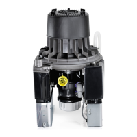
8.2 Electrical connections
WARNING
Electric shock
❯
The device may only be connected to a supply system with a earthed power outlet.
❯
Establish the electrical connection to the supply network (230 V).
– To a Dürr control box.
– Connected to a power outlet via the surgery's main power switch.
❯
Connection the display panel.
❯
Connect external start (optional).
❯
Connect external alarm (optional).
❯
Connect the network (when monitoring via the network).
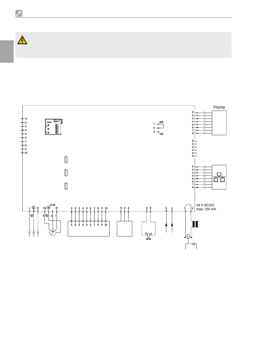
F1
F2
F3
X1
X2
230 V AC
1/N/PE
X3
-X100
X4 X7
X5
X6
24 V
AC/DC
X10
X8
X8a
X11
T 3,15 AH
T 4,0 AH
T 4,0 AH
X12
X14
X1
230 V AC power supply
X2 Motor connection
X3 Sensor system connection
X4.1 Emergency start sensor
X4.2 Reference sensor
X4.3 Water start sensor
X5 External start (optional input, protective low voltage 24V, AC/DC)
X6 External alarm (switching capacity max. 24V, 120mA, AC/DC)
X7 Relief valve connection
X8 Display panel connection (RJ45 connector)
Assembly
20 9000-606-44/30 2011V003
EN
 Loading...