❯
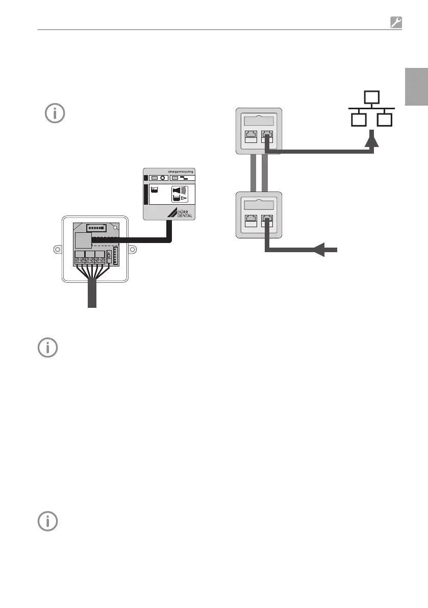
Connect the existing display cable to the termi-
nals of the adapter PCB.
– Ground terminal X2
– Screw terminals X3, X4, X5
(WH = white, YE = yellow, BU = blue, BN =
brown, PK = pink, GY = grey)
The colour coding complies with the
standard connection line system used
by Dürr.
❯
Plug the ISDN connecting cable of the display
panel into connector X6 on the adapter PCB.
❯
Mount the display panel in a suitable position.
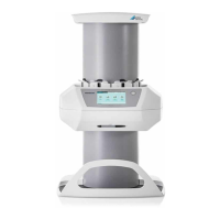
8.5 Network connection
All connected IT units must correspond to
the currently-valid edition of IEC 60950.
Purpose of the network connection
The network connection is used to exchange
information or control signals between the unit
and a software installed on a computer, in order
to, e. g.:
– Display parameters
– Select operating modes
– Indicate messages and error situations
– Change unit settings
– Activate test functions
– Transmit data for archiving
– Provide documents concerning the units
Connecting the device to the network
During initial installation, a router or server
with DHCP is recommended so the unit is
detected in the network.
❯
Remove the cover from the electronics.
❯
Plug the network cable into the electronics and
into a network socket.
❯
Attach the network cable to the device.
❯
Create a connection to the network in the sur-
gery with the network cable.
Assembly
9000-606-44/30 2011V003 25
EN
 Loading...