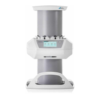
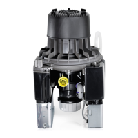
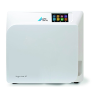
8.4 Display panel connection
The display panel is used to indicate mes-
sages acoustically and visually (via LEDs).
If the amalgam separator is set-up at a larger dis-
tance from the treatment chairs (e. g. in the
basement), the display panel must be installed
appropriately such that the status messages of
the amalgam separator can be monitored at all
times.
New installation with network sockets
There must be a direct line connecting the
RJ-45 socket on the unit and the RJ-45
socket on the display panel. Do not tog-
gle network units (e. g. switch or router).
Pay attention to the resistance of the net-
work cable between the RJ-45 sockets.
The maximum length should not exceed
50 m.
❯
Remove the cover from the electronics.
❯
Connect cable with RJ-45 socket to electron-
ics (X8) and in RJ-45 socket.
❯
Fix the cable to the unit.
❯
Connect display panel and RJ-45 socket using
the ISDN cable supplied.
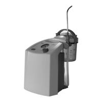
Replacement of an existing amalgam separa-
tor
Where a model 7801 amalgam separator
is being replaced by a CA 4 unit, the dis-
play panel can be connected using the
adapter cable provided. The shielding of
the existing display panel cable MUST
always be reconnected.
❯
Connect the yellow adapter cable to X8a on
the electronics.
❯
Connect the yellow adapter cable to the exist-
ing display cable.
❯
Connect the shielding of the display cable to
the ground point on the motor carrier.
❯
Fasten the cable to the strain relief on the floor
plate of the amalgam separator.
Replacement of large display panel with the
new, smaller display panel
Where a model 7801 amalgam separator
is being replaced by a CA 4 unit and the
smaller display panel supplied is to be
used, this can be connected with the help
of an adapter PCB (7805‑993‑00).
❯
Disconnect the wiring of the large display panel
in the terminal box and remove the terminal
strip (note colour coding).
Assembly
24 9000-606-44/30 2011V003
EN
 Loading...