Home
dynabook
Laptop
TECRA A50-J Series
dynabook TECRA A50-J Series User Manual
5
of 1
of 1 rating
167 pages
Give review
Manual
Specs
To Next Page
To Next Page
To Previous Page
To Previous Page
Loading...
Maintenance Manual (960-946)
B-4
Board Layout
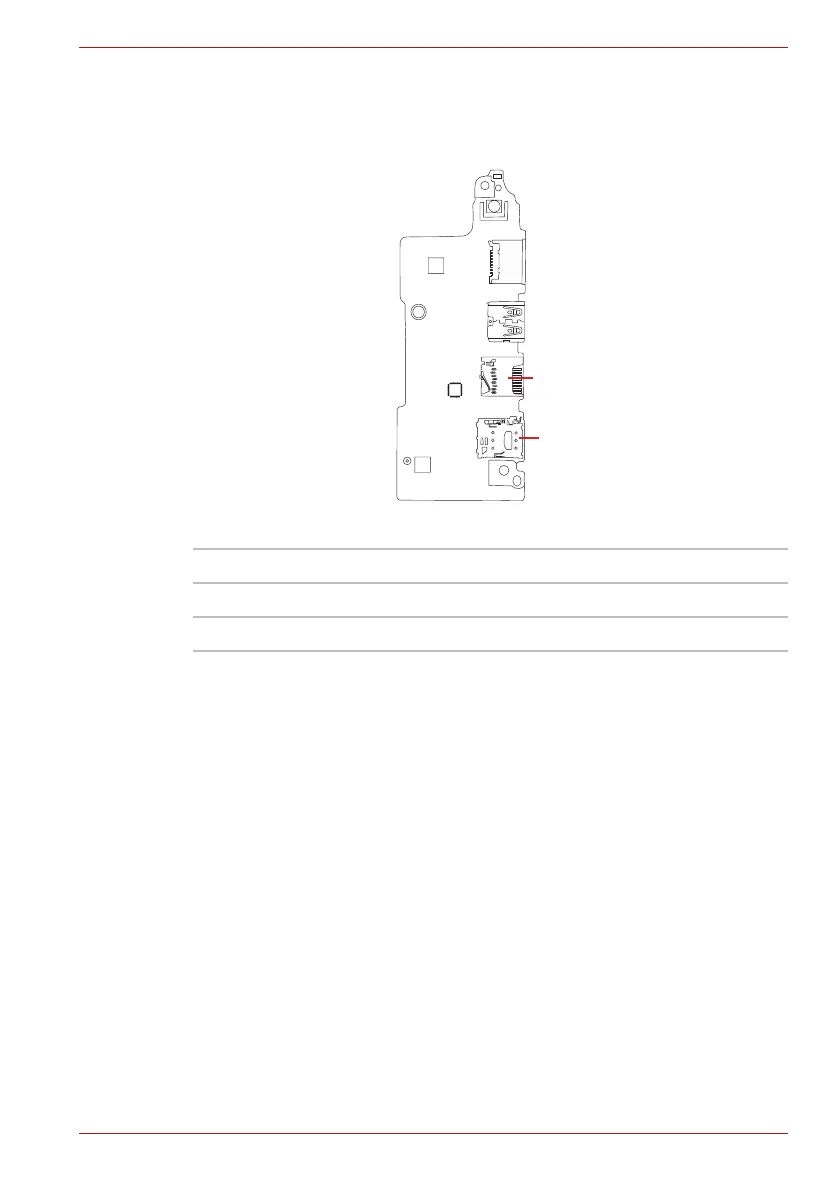
B.4 USB board (F
MERL
T*) Back V
iew
Figure B-4 USB board (FMERL
T*) layout (ba
ck)
T
able B-4 USB boa
rd (FMERL
T*) connectors (back)
Number
Name
IS2142
Micro SD I/F connector
IS2621
Nano SIM card I/F connector
IS2621
IS2142
127
129
Table of Contents
Default Chapter
5
Table of Contents
5
Chapter 1 Hardware Overview
12
Features and System Unit Block Diagram
12
Figure 1-1 System Unit Configurations
13
Figure 1-2 System Unit Block Diagram
14
Ssd
15
Figure 1-3 Keyboard
15
Table 1-1 M.2 SSD Specifications (KIOXIA)
17
Table 1-2 M.2 SSD Specifications (Phison)
17
Table 1-3 M.2 SSD Specifications (Samsung)
17
Keyboard
18
Display
18
Power Supply
19
Figure 1-4 LCD Module
19
Table 1-4 LCD Module Specifications
19
Table 1-5 Power Supply Output Rating
20
Batteries
21
Table 1-6 Battery Specifications
21
Table 1-7 Time Required for Charges
21
AC Adaptor
22
USB Type-C Adapter
22
Table 1-8 Data Preservation Time
22
Table 1-9 AC Adaptor Specifications
22
Table 1-10 USB Type-C Adapter Specifications
23
Chapter 2 Troubleshooting Procedures
24
Troubleshooting
24
Troubleshooting Flowchart
25
Figure 2-1 Troubleshooting Flowchart (1/2)
26
Figure 2-2 Troubleshooting Flowchart (2/2)
27
Power Supply Troubleshooting
29
Table 2-1 DC In/Battery Indicator
29
Table 2-2 Power Indicator
29
Table 2-3 Error Code
30
Figure 2-3 Connection Check
32
System Board Troubleshooting
33
USB Troubleshooting
34
Table 2-4 Main Test Menu
34
Figure 2-4 Connection Check
35
SSD Troubleshooting
36
Keyboard Troubleshooting
37
Touch Pad (Click Pad) Troubleshooting
38
Display Troubleshooting
39
Wireless LAN + Bluetooth Troubleshooting
40
LTE Troubleshooting
42
Sound Troubleshooting
44
Memory Media (SD Card) Slot Troubleshooting
45
Fingerprint Sensor Troubleshooting
46
Figure 2-5 Scan the Finger
46
Web Camera Troubleshooting
48
HDMI Port Troubleshooting
49
Figure 2-6 Connecting the HDMI out Port
50
LAN Troubleshooting
51
USB Type-C Adapter Troubleshooting
52
Chapter 3 Tests and Diagnostics
54
Test Program for Maintenance
54
How to Execute the Test Program
55
Entry of the DMI Information
57
Heatrun Test
59
Main Test Menu
59
Memory Test
61
Hard Disk (&SSD) Test
62
Keyboard Test
63
LCD Panel Test
64
Battery Charge Test
65
Fan Test
65
Log Utility
65
Wireless Module Test
66
Sound Test
68
Setup
68
Battery off Mode Setting Tool
74
Chapter 4 Replacement Procedures
77
Table 4-1 the Case for the Following Example
77
Safety Precautions
78
Before You Begin
79
Disassembly Procedure
80
Assembly Procedures
80
Figure 4-1 Pressure Plate Connector/Spring Connector/Back Flip Connector
80
Tools and Equipment
81
Screw Tightening Torque
81
Grip Color
82
Screw Notation
82
Memory Media
83
Figure 4-2 Inserting Memory Media
83
SIM Card (3G Model)
84
Figure 4-3 Installing the SIM Card
84
Cover Assembly and Base Assembly
85
Figure 4-4 Removing the Base Assembly (1)
85
Figure 4-5 Removing the Base Assembly (2)
86
Figure 4-6 Installing the Base Assembly
86
Battery Pack
87
Figure 4-7 Releasing the Battery Pack (1)
87
Figure 4-8 Releasing the Battery Pack (2)
88
Memory Module
89
Figure 4-9 Removing the Memory Module(S)
89
Ssd
90
Figure 4-10 Seating the Memory Module
90
Figure 4-11 Removing the SSD
91
Figure 4-12 Installing the SSD
91
Smart Card Slot
92
Figure 4-13 Removing the Smart Card Slot (1)
92
Figure 4-14 Removing the Smart Card Slot (2)
92
Figure 4-15 Removing the Smart Card Slot (3)
93
Figure 4-16 Removing the Smart Card Slot (4)
93
Wireless LAN Card
94
Figure 4-17 Removing the Wireless LAN Card
94
Module
95
Figure 4-18 Removing the 3G Module
95
Fans
96
Figure 4-19 Installing the 3G Module
96
Figure 4-20 Removing the Fans
96
Fin
97
Click Pad
97
Figure 4-21 Removing the Fin
97
Figure 4-22 Removing the Click Pad (1)
98
Figure 4-23 Removing the Click Pad (2)
98
Speaker
99
Figure 4-24 Installing the Click Pad
99
Figure 4-25 Removing the Speaker (1)
100
Figure 4-26 Removing the Speaker (2)
100
Antennas
101
Figure 4-27 Installing the Speaker
101
Figure 4-28 Removing the 3G Antennas (1)
102
Figure 4-29 Removing the 3G Antennas (2)
102
System Board
103
Figure 4-30 Removing the System Board (1)
103
Figure 4-31 Removing the System Board (2)
104
Figure 4-32 Removing the System Board (3)
104
Figure 4-33 Installing the System Board
105
DC in Jack
106
USB Board
106
Figure 4-34 Removing the DC in Jack
106
Keyboard/Cover Assembly
107
Figure 4-35 Removing the USB Board
107
Figure 4-36 Removing the Keyboard/Cover Assembly
108
LCD Assembly
110
Figure 4-37 Removing the LCD Unit (1)
111
Figure 4-38 Removing the LCD Unit (2)
112
Figure 4-39 Removing the LCD Unit (3)
112
Figure 4-40 Installing the LCD Unit (1)
113
Figure 4-41 Installing the LCD Unit (2)
113
Figure 4-42 Installing the LCD Unit (3)
114
Display Hinges
115
Figure 4-43 Installing the LCD Unit (4)
115
Figure 4-44 Removing the Display Hinges
115
Wireless LAN Antennas
116
Figure 4-45 Sticking the Wireless LAN Antennas
116
Camera Module
117
Figure 4-46 Arranging the Wireless LAN Antenna Cables
117
Figure 4-47 Removing the Camera Module (1)
117
Figure 4-48 Removing the Camera Module (2)
118
Figure 4-49 Installing the Camera Module (1)
120
Figure 4-50 Installing the Camera Module (2)
120
Appendix A Handling the LCD Module
121
Precautions for Handling the LCD Module
121
Board Layout
125
Appendix B Board Layout
125
System Board (FMERSY*) Front View
125
Figure B-1 System Board (FMERSY*) Layout (Front
125
Table B-1 System Board (FMERSY*) Connectors (Front
125
System Board (FMERSY*) Back View
126
Figure B-2 System Board (FMERSY*) Layout (Back
126
Table B-2 System Board (FMERSY*) Connectors (Back
126
USB Board (FMERLT*) Front View
127
Figure B-3 USB Board (FMERLT*) Layout (Front
127
Table B-3 USB Board (FMERLT*) Connectors (Front
127
USB Board (FMERLT*) Back View
128
Figure B-4 USB Board (FMERLT*) Layout (Back
128
Table B-4 USB Board (FMERLT*) Connectors (Back
128
Pin Assignments
129
Appendix C Pin Assignments
129
SYSTEM Board (FMERSY
129
Table C-1 CN1400 Memory Connector (260-Pin
130
Table C-2 CN1410 Memory Connector (260-Pin
134
Table C-3 CN1900 M.2 SSD Interface Connector
137
Table C-4 CN2630 WLAN Interface Connector
139
Table C-5 CN3240 KB Interface Connector (30-Pin
140
Table C-6 CN3270 KB Backlight Interface Connector (8-Pin
140
Table C-7 CN3380 FAN Interface Connector (4-Pin
141
Table C-8 CN3390 FAN Interface Connector (4-Pin
141
Table C-9 CN4800 USB Type-C Interface Connector (24-Pin
141
Table C-10 CN4821 USB Type-C Interface Connector (24-Pin
142
Table C-11 CN5590 HDMI Port (19-Pin
142
Table C-12 CN5390 Lcd/Webcam Interface Connector
143
Table C-13 CN8021 Battery Connector (17-Pin
144
Table C-14 CN9510 Click Pad Interface Connector (10-Pin
144
Table C-15 CN9550 Fingerprint Sensor Interface Connector (6-Pin
144
Table C-16 CN2170 Smartcard Slot (10-Pin
145
Table C-17 CN6290 L/F Speaker Connector
145
Table C-18 CN4850 USB Type-A Interface Connector
145
Table C-19 CN8001 DC-IN Connector
145
Table C-20 CN9600 FMERLT* Interface Connector (76-Pin
146
Table C-21 CN9601 FMERLT* Interface Connector (50-Pin
147
USB Board (FMERLT
148
Table C-22 J6320 Headphone/Microphone Jack (6-Pin
148
Table C-23 CN4810 USB Type-A Interface Connector
148
Table C-24 CN2650 SAR Connector
148
Table C-25 CN2610 M.2 (3G) Interface Connector
149
Table C-26 CN9640 FMERSY* Interface Connector (76-Pin
150
Table C-27 CN9641 FMERSY* Interface Connector (50-Pin
151
Table C-28 IS2142 Micro SD Card Interface Connector (13-Pin
152
Table C-29 IS2621 SIM Card Interface Connector
152
Table C-30 J4050 LAN Jack
152
Scan Codes
153
Table D-1 Scan Codes (Set 1 and Set 2
153
Table D-2 Scan Codes with Left Shift Key
157
Table D-3 Scan Codes in Numlock Mode
158
Table D-4 Scan Codes with Fn Key
158
Table D-5 Scan Codes in Overlay Mode
158
Table D-6 No.124 Key Scan Code
159
Table D-7 No.126 Key Scan Code
159
Appendix D Keyboard Scan/Character Codes
160
Key Layout
160
Appendix E Key Layout
160
United Kingdom (UK) Keyboard
160
United States (US) Keyboard
160
Figure E-1 UK Keyboard
160
Figure E-2 US Keyboard
160
Japan (JP) Keyboard
161
Figure E-3 JP Keyboard
161
RGB Monitor Loopback Connector
162
Figure F-1 RGB Monitor Loopback Connector
162
LAN Loopback Connector
163
Figure F-2 LAN Loopback Connector
163
Appendix F Wiring Diagrams
164
BIOS Rewrite Procedures
164
Tools
164
Rewriting the BIOS
164
Appendix G BIOS Rewrite Procedures
166
EC/KBC Rewrite Procedures
166
Appendix H EC/KBC Rewrite Procedures
167
Reliability
167
Table I-1 MTBF
167
5
Based on 1 rating
Ask a question
Give review
Questions and Answers:
Need help?
Do you have a question about the dynabook TECRA A50-J Series and is the answer not in the manual?
Ask a question
dynabook TECRA A50-J Series Specifications
General
Brand
dynabook
Model
TECRA A50-J Series
Category
Laptop
Language
English
Related product manuals
dynabook TECRA A50-K
175 pages
dynabook TECRA A40-G
127 pages
dynabook TECRA A40-K
141 pages
dynabook Tecra A30-G
128 pages
dynabook TECRA A4 K Series
175 pages
dynabook TECRA A40-J Series
165 pages
dynabook Portege X30L-G
120 pages
dynabook SATELLITE PRO C50-G
143 pages
dynabook Satellite Pro C50-J
143 pages
dynabook SATELLITE PRO C50-K
145 pages
dynabook PORTEGE X40-J Series
159 pages
dynabook Portege X30L-K Series
39 pages
 Loading...