Do you have a question about the dynabook TECRA A50-J Series and is the answer not in the manual?
| RAM | Up to 32GB DDR4 |
|---|---|
| Storage | Up to 1TB PCIe Gen4 NVMe SSD |
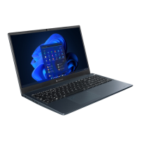
| Display | 15.6-inch FHD (1920 x 1080) |
| Graphics | Intel Iris Xe Graphics |
| Operating System | Windows 10 Pro |
| Ports | HDMI |
| Wireless | Wi-Fi 6 (802.11ax) |
| Bluetooth | Bluetooth 5.1 |
| Security | TPM 2.0, Fingerprint Reader |
| Dimensions | 19.9 mm |
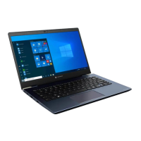
Describes the computer's features, major components, and system unit configuration.
Details the M.2 SSD specifications, including capacities and physical dimensions.
Explains the functions of the power supply and its voltage outputs to the system board.
Provides specifications for the main battery pack and details on its charging control.
Guides on determining which Field Replaceable Unit (FRU) causes a computer malfunction.
Provides flowcharts to guide the execution of troubleshooting procedures for diagnosing issues.
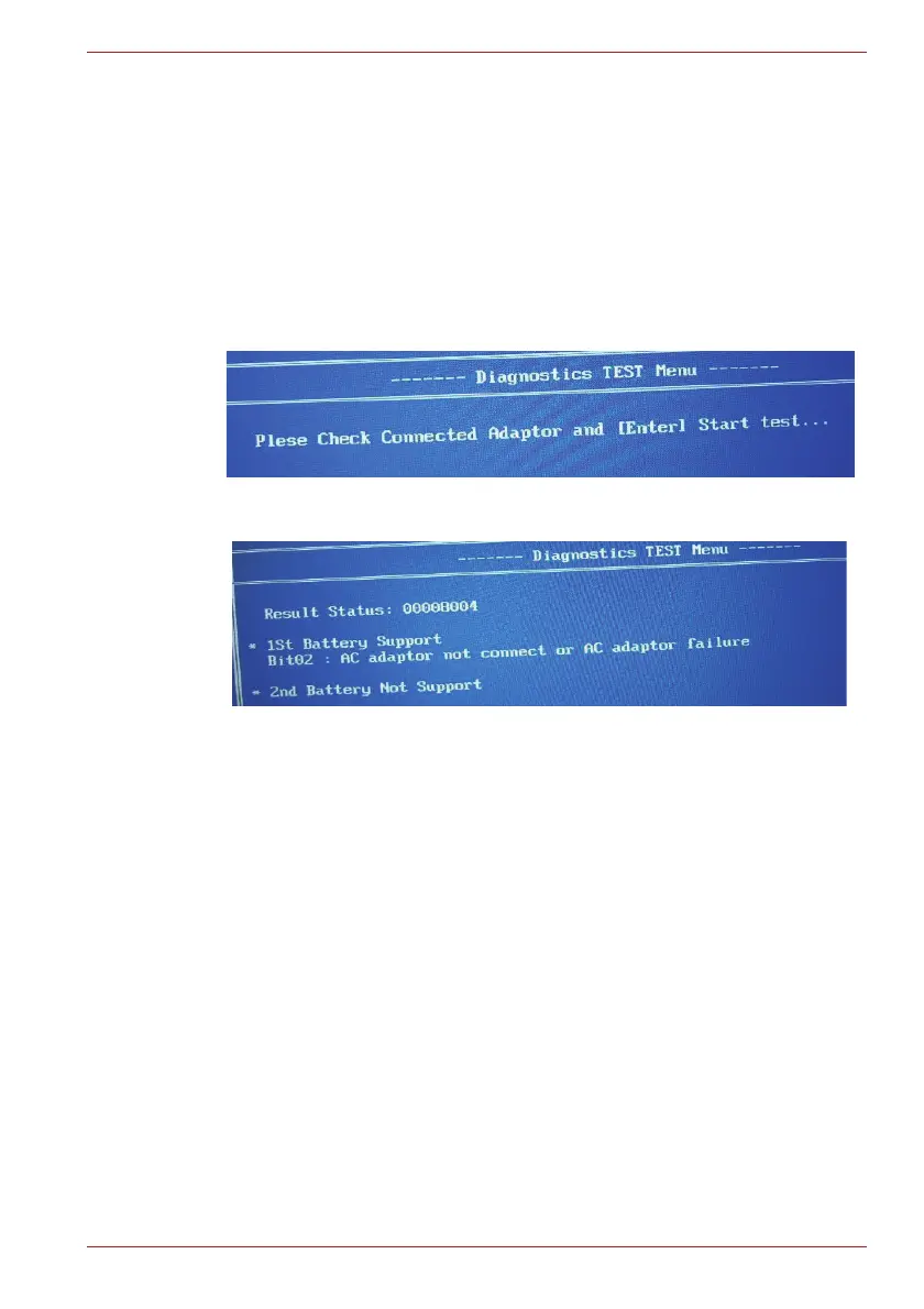
Outlines procedures to check the power supply status, error codes, and connections.
Describes how to determine if the system board is malfunctioning through message checks and diagnostic tests.
Details procedures for checking USB functionality, including connector checks and replacement.
Guides on troubleshooting M.2 SSD issues, covering diagnostic tests and connector checks.
Provides steps to check keyboard functionality, including diagnostic tests and connector checks.
Outlines procedures to troubleshoot Touch Pad issues, including connector checks and replacement.
Describes how to check display functionality and troubleshoot issues via OS checks and diagnostic tests.
Guides on troubleshooting Wireless LAN and Bluetooth module issues, including connection and replacement.
Details procedures for troubleshooting 3G/LTE module installation, antenna/connector checks, and replacement.
Provides steps to check sound functionality, including OS checks, connector checks, and replacement.
Guides on troubleshooting the memory media (microSD Card) slot, including OS checks and connector checks.
Outlines procedures for troubleshooting fingerprint sensor issues, including setup and connector checks.
Details steps to troubleshoot web camera malfunctions, including OS checks and connector checks.
Guides on troubleshooting HDMI port issues, covering connection checks and replacement.
Provides procedures for troubleshooting LAN functionality, including OS checks and connector checks.
Outlines steps to troubleshoot USB Type-C adapter functions, including RGB port and connector checks.
Lists the items included in the test program for hardware maintenance and updates.
Provides step-by-step instructions on how to start and run the maintenance test programs.
Details the procedure for entering and registering DMI information, especially after system board replacement.
Details the procedure for executing the main memory test and its subtests.
Explains how to perform hard disk and SSD tests, including sequential read and partial read tests.
Describes the keyboard test, including key-code and touch pad tests.
Details the LCD panel tests, covering color display, dot tests, and brightness adjustments.
Guides on checking wireless module and antenna functionality through Windows and PC information.
Lists essential safety instructions to follow before disassembling the computer.
Explains the four main types of cable connectors and their disconnection/reconnection procedures.
Covers the general points to consider when reassembling the computer after repair or replacement.
Guides on removing and installing the system board, including DMI, BIOS, and EC/KBC updates.
Details the procedure for removing and installing the LCD unit, including mask and camera panel.