Section 9: Control accessories
The CL-6 voltage regulator control has several accessory
features available. Accessories available include
communications software and hardware, a heater assembly,
and a PC-to-dataport cable.
Communications
Software
ProView NXG software
Eaton's Cooper Power series ProView NXG software was
developed as an advanced package to configure, program,
and acquire data from CL-6 series voltage regulator controls.
ProView NXG allows the user to:
•
Create control settings
•
Upload control settings
•
Download control settings
•
Provide output of settings and readings
•
Manage settings and readings effectively
ProView NXG software is fully compatible with the
Microsoft
®
Windows
®
95 or later operating system, with
Microsoft
®
Windows NT
®
Workstation Version 4.0 or
later operating system, and the Microsoft
®
Windows
®
XP
operating system. Both readings and settings are stored
as convenient Microsoft
®
Excel (.XLS) format files to allow
use of the data by other applications without awkward
conversions.
ProView NXG software is a user-friendly, graphically oriented
program that is easy to use and understand. On-line help
and a complete user manual help make the program one
of the most comprehensive in the industry. The software
is designed for configuration of the regulator control using
Data 2179 and DNP3 protocols.
Hardware
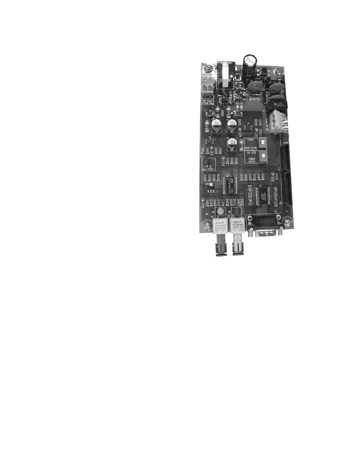
Fiber-optic with RS-232 interface board
In this configuration, a pair of standard ST type fiber-optic
connectors and an RS-232 port are mounted on the
interface board to provide the customer connection to digital
SCADA via multi-mode fiber-optic cables or a standard
9-pin DB-9 RS-232 cable. Communication settings are
easily changed with the use of DIP switches or through the
ProView NXG software package. The fiber-optic connections
are used for fiber looping (fiber loop or fiber star) with
other controllers. The RS-232 interface provides for primary
external communication with the control. In the event
where multiple controls are being interconnected, only
one device requires connection to the RS-232 port, while
the remaining devices communicate through the fiber-
optic connections. See Figure 9-1 for sample connection
diagrams.
Ethernet interface board
In this configuration, an RJ-45 and ST fiber connectors are
mounted to the interface board. These provide the customer
with digital SCADA via standard cat 5 cable or multimode
fiber.
RS-485 Interface Board
In this configuration, RS-485 twisted pair terminals are
mounted on the interface board to provide the customer
connection to digital SCADA via a twisted pair RS-485
connection.
Heater assembly
A thermostatically controlled heater assembly is available
for use in high-humidity areas. The thermostat in the heater
assembly will turn the heater on when the temperature falls
below 85 °F (29 °C) and off when the temperature exceeds
100 °F (38 °C). For full details refer to Service Information
S225-10-12 VR-32 Regulator Control Heater Part No. 9000:
Installation and Parts Replacement Instructions.
Figure 9-1. Fiber-optic with RS-232 Interface Board.
108
CL-6 SERIES CONTROL INSTALLATION, OPERATION, AND MAINTENANCE INSTRUCTIONS MN225016EN January 2016
 Loading...


