Programming and reconfiguring for different voltage
systems
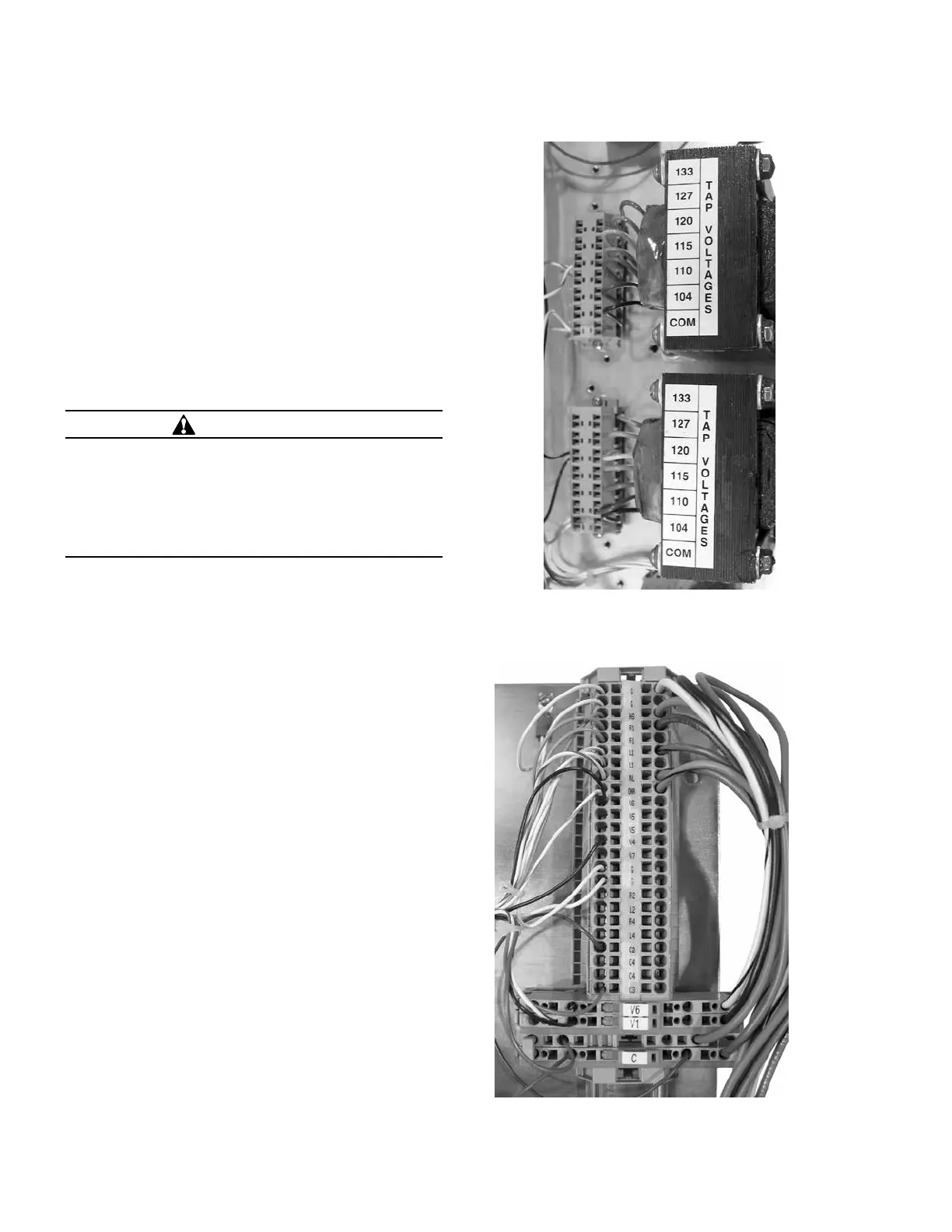
Reconfiguring regulators requires more than just
reprogramming the control. In reconfiguring, refer to the
nameplate and, if necessary, change the connection of
the ratio-correcting transformers (RCTs) on the back panel
(see Figure 3-1). In some cases, it may be necessary to
reconnect the tap windings in the regulator via the hand-
hole cover.
Refer to the nameplate for information on programming and
reconfiguring a regulator: confirm Regulator Configuration
(FC 41), System Line Voltage (FC 43), and Overall PT Ratio
(FC 44). Refer to Allowable System Voltages and
Calculation of Overall PT Ratio and Determination
of Leading or Lagging in Delta-Connected
Regulators, in this section of the manual.
1. Start with all switches on the control front panel turned Off.
2. Refer to the nameplate. If the Control Winding Taps are
required to be changed to reconfigure, de-energize the
regulator. Open up the hand hole and reconnect the E
tap lead on the tap-changer terminal board on top of the
tap-changer. (Example: If the regulator is being changed
from a 7200 to 14400 load voltage, the Control Winding
tap needs to be changed from E
2
to E
1
.) See Figure
3-3 for nameplate information.
3. Open V1 switch and, if present, V6. Refer to Figure 3-2.
4. Connect the RCT per the information supplied by the
nameplate. The RCT is to be connected to the value listed
on the nameplate for the load voltage to be regulated. The
adjustable lead is tagged and has a loop in it.
5. Close V1 switch and, if present, V6.
6. There are two options for powering the control panel:
internal power or external power. Select one method
and follow the appropriate step.
A. Internal Power
Turn POWER switch to Internal Power from the
Off position.
B. External Power
Apply external source to EXTERNAL SOURCE binding
post: hot lead to black, top binding post; neutral lead
to white bottom binding post; ground to green ground
binding post. Turn POWER switch to External power
from the Off position. See the detailed instructions
for applying power to the external source terminals in
Section 1 of this manual.
Figure 3-2. V1, V6, and C connections.
Figure 3-1. Ratio-correcting transformers’ connections.
WARNING
Explosion Hazard. Bypass a regulator with the line
energized only if both the position indicator and the
neutral light indicate neutral. If both do not indicate
neutral, the line should be de-energized to avoid
shorting part of the series winding and resultant high
circulating current. Failure to comply can result in death
or personal injury and equipment damage.
20
CL-6 SERIES CONTROL INSTALLATION, OPERATION, AND MAINTENANCE INSTRUCTIONS MN225016EN January 2016
 Loading...


