Reverse power operation
Most voltage regulators are installed in circuits with well-
defined power flow from source to load. However, some
circuits have interconnections or loops in which the direction
of power flow through the regulator may change. For
optimum utility system performance, a regulator installed on
such a circuit should have the capability of detecting reverse
power flow and of sensing and controlling the voltage,
regardless of the power flow direction.
The control has full reverse power capabilities. For fully
automatic reverse operation, the source voltage must be
available to the control. Refer to Source-Side Voltage in
this section of the manual.
The control offers seven different response characteristics
for reverse-power detection and operation. These
characteristics are user-selectable by programming
the Reverse Sensing Mode (FC 56). The seven modes
are Locked Forward, Locked Reverse, Reverse Idle,
Bi-directional, Neutral Idle, Cogeneration, and Reactive
Bi-directional.
This section will separately explain each mode of operation.
Since the control retains the reverse metered demand
values separate from the forward metered values, the
metering will also be explained for each mode.
In determining power direction, the control senses the real
component of the current (except in reactive bi-directional
mode), then determines the current direction and magnitude
in that direction. When the conditions indicate the power
is flowing in reverse, the following parameters assume new
values and the control operation is affected accordingly:
Load Voltage Now sensed from what was previously
the source voltage supply.
Source Voltage Now sensed from what was previously
the load voltage supply.
Load Current In the forward direction, the current is
used directly as measured. In the reverse
direction, the current is scaled to reflect
the ratio difference between the source
and load side of the regulator, according
to this formula
Q
:
Q
Where source voltage supply and load
voltage supply are in the reverse direction.
Based upon the new metered reverse values, the kVA, kW,
kvar, and % buck/boost are now calculated.
Locked forward mode
When FC 56 is set for Locked Forward, no source voltage
is required. This mode is not intended to be used in
applications where reverse power flow is possible.
METERING: Always operates in the forward direction,
regardless of power flow direction. If reverse power occurs,
the metering functions remain on the normal load side of
the regulator—no reverse demand readings will occur.
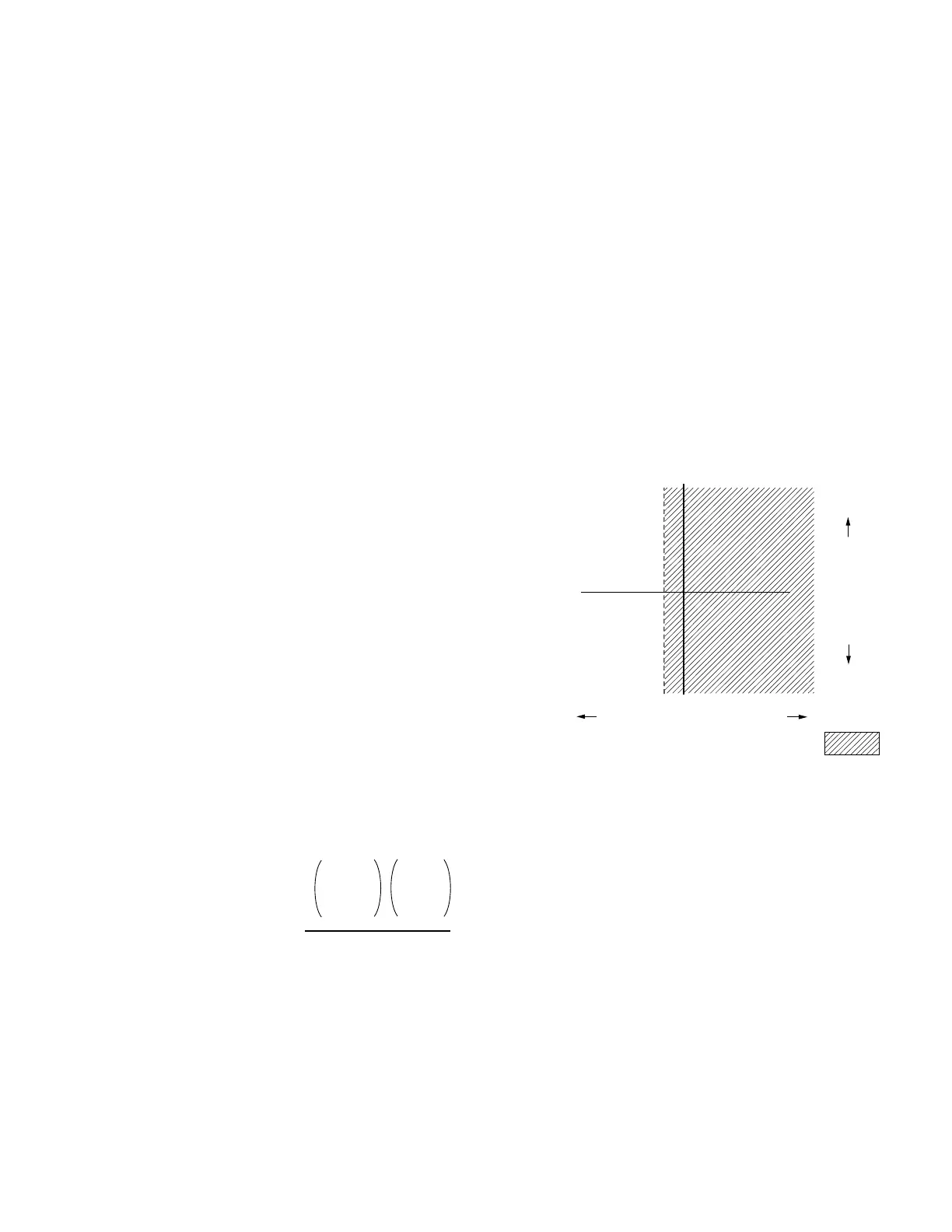
OPERATION: (Figure 6-2) Always operates in the forward
direction using the forward settings at FC 1, FC 2, FC 3,
FC 4, and FC 5. This allows operation down to zero current
conditions since there is no forward threshold involved.
A safeguard has been built into the control to prevent
misoperation in the event reverse power flow does occur.
If more than 2% (.004 A CT secondary) reverse current
occurs, the control idles on the last tap position held and
the band edge indicators will turn off. As the current flow
returns to a level above this reverse threshold, normal
forward operation resumes.
Figure 6-2. Locked forward mode operation.
Locked reverse mode
When FC 56 is set for Locked Reverse, source voltage
is required. This mode is not intended to be used in
applications where forward power flow is possible.
METERING: Always operates in the reverse direction,
regardless of power flow direction. If forward power occurs,
the metering functions remain on the source (S bushing)
side of the regulator and no forward demand readings will
occur.
Reactive Current
Real Current (% of C.T. Primary)
Forward Operation =
2% 0
Band edge indicators
are turned off and tap
changing is inhibited
when real component
of current is greater
than 2% reverse.
Reverse Load Current =
Load Voltage Supply
Forward
Load
Current
Source
Voltage
Supply
79
CL-6 SERIES CONTROL INSTALLATION, OPERATION, AND MAINTENANCE INSTRUCTIONS MN225016EN January 2016
 Loading...


