Remote motor control and auto inhibit
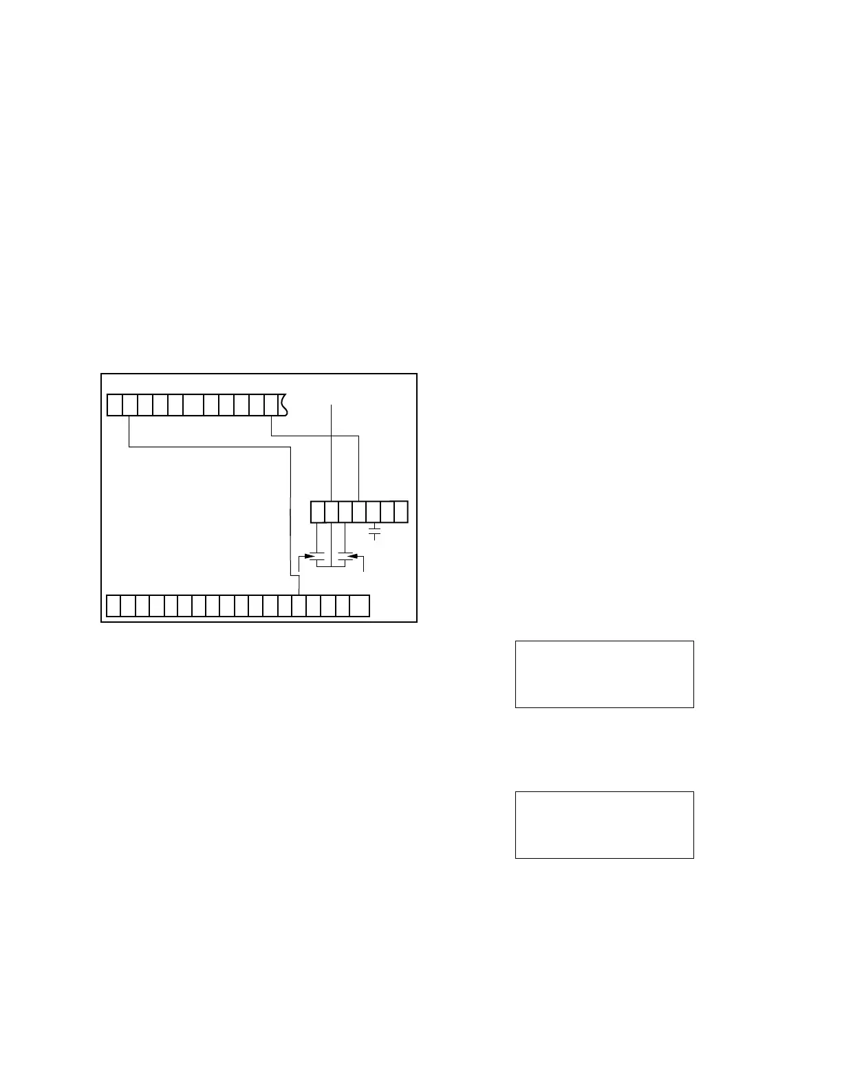
Note: Terminal board TB
8
, located below RCT
1
on the
control back panel, is supplied for user-connections
for Auto Inhibit (blocking) and Motor Control. See
Figure 6-15. When the motor is controlled remotely,
it is necessary to inhibit automatic operation. To
control Auto Inhibit remotely, remove the jumper
between terminals 4 and 5 and supply a nominal
120 Vac to terminal 5. This will inhibit automatic
operation.
To remotely raise or lower the tap-changer, the appropriate
set of contacts is momentarily closed. If user-provided
interposing relays are used, such that raise and lower
contact closure cannot occur simultaneously, the operator
should make a permanent connection from TB
2
-V
9
to TB
8
-2.
For units supplied with TB
3
back panel (after
October, 2010)
When the motor is controlled remotely, it is necessary to
inhibit automatic operation. To control Auto Inhibit remotely,
supply a nominal 120 Vac to terminal BR (Blocking Relay) on
TB
3
. This will inhibit automatic operation.
To remotely raise or lower the tap-changer, the appropriate
set of contacts is momentarily closed. A user provided
interposing relay is recommended, such that the raise
and lower contact closure cannot occur simultaneously. A
120 Vac voltage is required at R1 for raise or L1 for lower.
Whetting voltage can be obtained from terminal TB
3
-V9.
Alternate configuration
The CL-6 control panel typically operates with one set of
configuration settings that are programmed or changed
through the keypad or one of the available communi-
cations channels using ProView NXG software (see
Communications in the Control Accessories section of this
manual for more information on ProView NXG software).
The Alternate Configuration mode allows for the CL-6 control
to be programmed with an additional set of configuration
settings that can then be activated at FC 450. The Alternate
Configuration status can be monitored at FC 451 and will
display either Active or Inactive.
When the Alternate Configuration mode is activated
using FC 450, the set of alternate configuration settings
will become active and will be used as the basis for the
operation of the control. The control parameters included
in the set of Alternate Configuration settings are: Forward
Direction (FC 1 through FC 5), Reverse Direction (FC 51
through FC 55), Auto-Block Status (FC 69), Reverse Power
Mode (FC 56), Voltage Limiter (FC 80 through FC 82),
Voltage Reduction (FC 70 and FC 72 through FC 75), Tap-To-
Neutral (FC 170) and Soft ADD-AMP (FC 79 and FC 175
through FC 176).
Alternate Configuration settings can be entered using two
methods: 1) Activate the Alternate Configuration mode by
turning it on at FC 450 and then set the individual settings
using each function code. 2) Using ProView NXG software,
enter the Alternate Configuration settings in the Alternate
Configuration Setting screen and load the settings using one
of the communications channels.
When the control is in the Alternate Configuration mode,
the display for each of the affected control parameters will
display the statement “(AltConfig)” at the bottom. This will
indicate that the alternate configuration setting is active and
in use for control operation (see the example below).
001 Forward
Set Voltage
120.0 Volts
(AltConfig)
When the Metering-PLUS Comp Voltage button is pressed,
it will display “AltConfig Active” on the bottom line as
shown in the example below.
Comp Voltage 120.0
Band 119.0-121.0
Using Func 1-5
AltConfig Active
Figure 6-15. Auto inhibit and remote motor
control connections.
V
5
V
S
L
1
R
1
NLHSG
DHR
TB
2
TB
1
TB
8
V
9
V
7
V
S
V
M
C
1
C
3
HS R
3
L
3
NL
DHR
8 7 6 5
BR
J G
1 2 3 4 5 6 7
G
Rear Panel
Lower
Raise
M
Power
from Pin 14,
PIO Port
TB
2 -
V
9
87
CL-6 SERIES CONTROL INSTALLATION, OPERATION, AND MAINTENANCE INSTRUCTIONS MN225016EN January 2016
 Loading...


