Bi-directional mode
When FC 56 is set for Bi-directional, source voltage is
required. This mode is recommended for all installations
where reverse power flow may occur except where the
source of reverse power is a cogeneration facility or
independent power producer.
METERING: (Figure 6-6.) A threshold level of 1% (.002 A)
of the full load CT secondary current (.200 A) is used in
setting the power direction. The metering will be forward
until the current exceeds the 1% threshold in the reverse
direction. At this time, the various parameters use the
reverse settings and the Reverse Power indicator turns on.
The control continues metering in reverse until the current
exceeds the 1% threshold in the forward direction, and
then the parameter scaling reverts back to normal and the
Reverse Power indicator turns off.
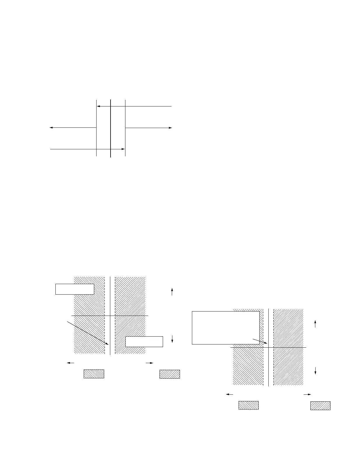
OPERATION: (Figure 6-7.)The control operates in the
forward direction whenever the real component of the
current is above the operator defined forward threshold
(FC 57). The control operates in the reverse direction, using
the reverse settings at FC 51, FC 52, FC 53, FC 54, and
FC 55, whenever the current is above the operator defined
reverse threshold (FC 57). When the current is in the region
between the two thresholds, the control idles on the last
tap position held before the current fell below the threshold.
The operational timer (time delay) is reset on any excursion
below the threshold in either direction, and the band edge
indicators turn off.
Neutral Idle mode
When FC 56 is set to Neutral Idle, a source voltage is
required.
METERING: (Figure 6-6) A threshold level of 1% (.002 A)
of the full load CT secondary current (.200 A) is used in
setting the power direction. The metering will be forward
until the current exceeds the 1% threshold in the reverse
direction. At this time, the various parameters use the
reverse settings and the Reverse Power indicator turns on.
The control continues metering in reverse until the current
exceeds the 1% threshold in the forward direction, and
then the parameter scaling reverts back to normal and the
Reverse Power indicator turns off.
OPERATION: (Figure 6-8) The control operates in the
forward direction whenever the real component of the
current is above the operation-defined forward threshold
(FC 57). When the current exceeds the operator-defined
reverse threshold (FC 57) and is held for 10 continuous
seconds, the control will tap to neutral. Neutral position
is determined using Tap Position. If the tap position is not
valid, neutral is determined using percent regulation (buck
and boost). When the current is in the region between the
two thresholds, the control idles on the last tap position
held before the forward threshold was crossed. While
tapping to the neutral position, if the current falls below the
reverse threshold, the control continues to tap until neutral
position is reached. The operational timer (time delay) is
reset on any excursion below the forward threshold, and
the band edge indicators turn off.
Figure 6-6. Bi-directional, neutral idle and reactive bi-
directional metering.
Normal Forward
Metering
Rev Pwr Off
Reverse Metering
Reverse Scaling
Rev Pwr On
Current Level
1% 0 1%
Figure 6-7. Bi-directional mode operation.
Reactive Current
Real Current (% of C.T. Primary)
Forward Operation =
0
OT
OT=Operating Threshold, FC 57, 1-5%
Tap changing
inhibited and
band edge
indicators are
turned off.
Reverse Operation =
OT
Normal Reverse
Operation FC 51-55
Normal Forward
Operation FC 1-5
Figure 6-8. Neutral idle mode* operation.
Reactive Current
Real Current (% of C.T. Primary)
Forward Operation =
0
OT
OT=Operating Threshold, FC 57, 1-5%
Band edge indicators are
turned off and tap changing
is inhibited when real
component of current is at or
below the operation threshold,
FC 57, in either direction.
Tap-to-Neutral =
OT
* Band edge indicators are turned off.
81
CL-6 SERIES CONTROL INSTALLATION, OPERATION, AND MAINTENANCE INSTRUCTIONS MN225016EN January 2016
 Loading...


