Reactive bi-directional mode
When FC 56 is set for Reactive Bi-directional, source voltage
is required.
This mode is recommended for installations where reverse
power flow may occur and the real component of the
current is below the operator-defined threshold (FC 57),
except where the source of reverse power is a cogeneration
facility or independent power producer.
METERING: (Figure 6-12.) A threshold level of 1% (0.002 A)
of the full load CT secondary current (0.200 A) is used in
setting the power direction. The metering will be forward
until the current exceeds the 1% threshold in the reverse
direction. At this time, the various parameters use the
reverse settings and the Reverse Power indicator turns on.
The control continues metering in reverse until the current
exceeds the 1% threshold in the forward direction, then the
parameter scaling reverts back to the normal and Reverse
Power indicator turns off.
OPERATION: (Figure 6-12.) The control determines which
settings (forward/reverse) to use by sensing the real and
reactive components of the current. The control operates in
the forward direction whenever the magnitude of the reactive
component of the current exceeds the operator-defined
threshold (FC 57) in the negative direction. The control also
operates in the forward direction if the magnitude of the
real component of the current exceeds the operator-defined
threshold (FC 57) in the positive direction while the magnitude
of the reactive component of the current is between the
operator-defined thresholds (FC 57). The control operates in
the reverse direction using the reverse settings at FC 51, FC
52, FC 53, FC 54, and FC 55 whenever the magnitude of
the reactive component of the current exceeds the operator-
defined threshold (FC 57) in the positive direction. The control
also operates in the reverse direction if the magnitude of the
real component of the current exceeds the operator-defined
threshold (FC 57) in the negative direction while the magnitude
of the reactive component of the current is between the
operator-defined thresholds (FC 57).
Voltage limiter
The voltage-limiter feature is used to place high and low
limits on the output voltage of the regulator. Voltage Limiter
is equipped with both standard and Integrated Volt/Var
Control (IVVC) modes of operation; the IVVC options are
used when voltage is being regulated through SCADA.
Voltage Limiter operates in either the forward or reverse
directions.
When the standard modes are enabled, Voltage Limiter has
one of the highest priorities of all operating functions and
is overridden only when the control switch is set to Off or
Manual, when Auto Operation Blocking Status (FC 69) is set
to Blocked, when an operator takes local control or through
an inter-connected SCADA system. When the IVVC modes
are used, Voltage Limiter will take an even higher priority by
operating to limit voltage at the set limits, even when FC69
is set to Blocked. In addition, it will limit SCADA tapping
commands if the control voltage is either at a set limit or
when the next tap change will take it over a limit.
The purpose of the Voltage Limiter is to protect the
consumer from abnormally high or low voltages resulting
from:
•
Large, rapid changes in transmission voltage
•
Abnormal loading of the feeder
•
Inaccurate regulator control settings (voltage level,
bandwidth, and line-drop compensation)
•
Heavy loading by the first customer while there is a
leading power factor on the feeder
•
Light loading at the first customer with heavy loading on
the feeder at the same time
The appropriate high and low limits for the output voltage
can be programmed into the control at FC 81 and FC 82,
respectively. The feature is then activated by accessing
FC80 and entering the desired operation: Off; High Limit
only; High/Low Limits; IVVC High Limit Only; and IVVC High/
Low Limits. If low-voltage limiting only is desired, FC 80
should be set to both high and low limiting to enable this
limit and the value programmed into FC 81 for the high
limit can be set to some extreme number (such as 135) to
prevent the high limit from activating.
The control has two response sensitivities. If the output
voltage exceeds either the high or low limit by
3 V or more, the control samples the voltage for two
seconds and then taps immediately to bring the voltage
to the limit value. If the output voltage exceeds either the
high or low limit by less than 3 V, the control samples the
voltage for 10 seconds then taps to bring the voltage to the
limit value. The 10-second delay is used to prevent false
responses to transient conditions. The control uses the
sequential method of tapping, a two-second pause between
taps for voltage sampling, when bringing the voltage back to
the limit value. Voltage Limiter High and Voltage Limiter Low
indicators in the display indicate when either limit is active.
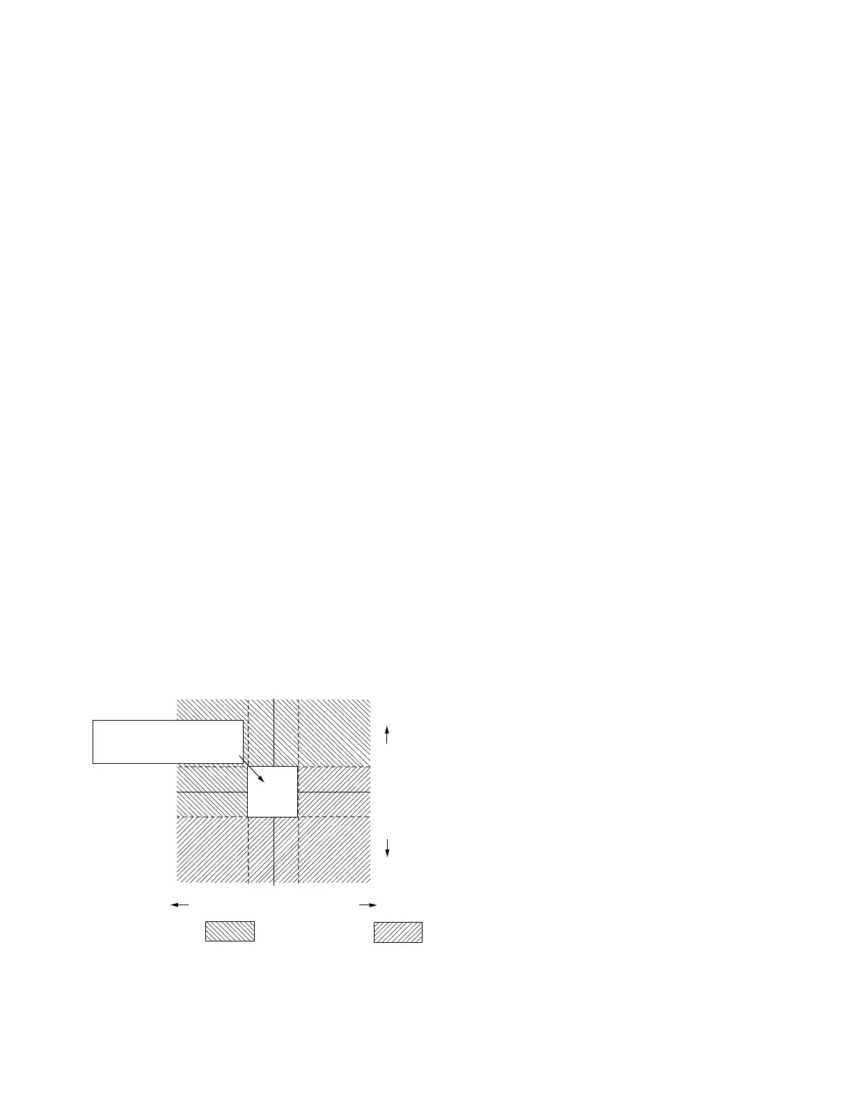
Figure 6-12. Reactive bi-directional mode
operation.
Reactive Current
Real Current (% of C.T. Primary)
Forward Operation =
0
OT
OT=Operating Threshold, FC 57, 1-5%
Tap changing inhibited
when total current is
within operating thresholds.
Reverse Operation =
OT
+
83
CL-6 SERIES CONTROL INSTALLATION, OPERATION, AND MAINTENANCE INSTRUCTIONS MN225016EN January 2016
 Loading...


