5.2 Conguration Steps
5.2.1
Device Planning
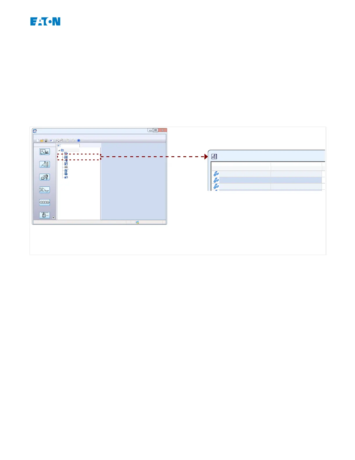
Enter the menu [Device Planning] and activate or disable all the modules and protection
functions that are required for your application.
In the »Device Planning« dialog, double-click every required module and set it to “Use”.
Modules that are not required should be set to “-”.
This denes the functional range of the protection device.
E_FBJ
Device connectedReady
Shortcuts
Data from Device
PowerPort-E
File Device Edit View Settings Tools Window Help
?
Operation
Device Planning
Device Para
1,0
System Para
50/60
Protection Para
7
6
5
EGR-5000
Operation
Device Planning
Device Para
System Para
Protection Para
Control
Logic
Service
Ctrl . Single Line BusbarFeeder
IH2 . Mode -
50P[1] . Mode -
Fig. 8: Double click [Device Planning] and select the required protection and supervision
modules.
5.2.2
Measurement Display
Enter the menu [Device Para / Measurem Display / General Settings] and set the
parameter »Scaling« to either “Per unit values”, “Primary values” or “Secondary values”.
This denes how the measured values shall be displayed.
5.2.3
Digital Inputs
Enter the menu [Device Para / Digital Inputs] and all sub-menu items therein (depending
on your hardware, i. e. which slot are tted with digital inputs), for example [Device Para /
Digital Inputs / DI Slot X1 / Group 1]. Set the parameter »Nom Voltage« to either “24 Vdc”,
“48 Vdc”, “60 Vdc”, “125 Vdc”, “250 Vdc”, “110/120 Vac”, “230/240 Vac”.
This denes the nominal voltage of the binary input.
In the same way set and/or check the other settings, »Inverting x« and »Debouncing
Time x«
This denes the whether the binary input shall be inverted, and which time interval shall be
used for the input signal to avoid misinterpretation due to bouncing eects.
75www.eaton.comE-Series Family Quick Start Guide
5 Conguration via PowerPort-E
5.2 Conguration Steps
 Loading...