Installation procedure
20 CBC-8000 capacitor bank control installation and operation instructions MN916001EN—October 2018 Eaton.com
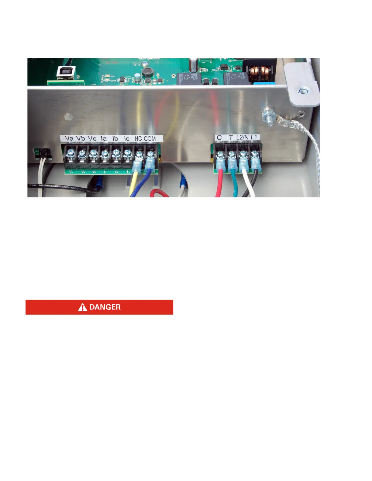
Figure 21. CBC-8000 control terminal block inputs.
Installing the control
Perform the following steps to install the control:
1. Measure the distance between the installation location
of the control and the live parts of the capacitor bank.
• If the CBC-8000 control is replacing an existing control
device and the distance meets locally approved safety
standards, skip to step 2.
• If the distance does not meet locally approved safety
standards, or a neutral or line post sensor is being
installed, perform the following steps:
a. Trip (open) the capacitor bank.
Hazardous voltage.
Residual capacitive voltage may be present in the
capacitors after discharging.
Follow the appropriate shorting procedure to discharge
any residual voltage.
Failure to comply can result in serious injury or death.
C1107.0
b. Do not ground the capacitor bank immediately after
the bank has been disconnected from the system
(tripped). Instead, wait five to ten minutes before
grounding, depending on the discharge time of the
capacitors.
c. Isolate the capacitor bank and prepare for grounding
by opening the line fuse or disconnect on each phase.
This provides a visible open indication.
d. Use a shorting stick with an insulated handle to
ground all parts of the capacitor bank before touching
frames or terminals. In addition, ground the neutral of
ungrounded capacitor banks.
e. Use a shorting wire to connect the capacitor
terminals together and to the case.
2. For the correct wiring of the meter socket, refer to
Figure 27 and Figure 28 for a diagram of the four-jaw and
six-jaw meter socket configurations.
The control enclosure is available in four-jaw, six-jaw, or
pole mount configurations. To determine the mounting
configuration, look at the sixth character in the style
number.
• C8020110 – The sixth character of the style number is 1.
Therefore, the mounting configuration of the control is
four-jaw. For instructions on installing a control with a
four-jaw configuration, see
Socket mount installation
on Page 25.
• C8020310 – The sixth character of the style number is 3.
Therefore, the mounting configuration of the control is
six-jaw. For instructions on installing a control with a six-
jaw configuration, see
Socket mount installation on
Page 25.
• C8020810 – The sixth character of the style number is 8.
Therefore, the mounting configuration of the control is
pole mount. For instructions on installing a control with a
pole mount configuration, see
Pole mount installation
on Page 26.

 Loading...


