Approved sensor manufacturers
40 CBC-8000 capacitor bank control installation and operation instructions MN916001EN—October 2018 Eaton.com
Approved sensor manufacturers
The CBC-8000 control supports measurements from both
line post and neutral current sensors.
The sensor inputs for the control are rated for 0 to 10 VAC.
Note: If you are using a sensor that is not on the approved
list, refer to the Communications Point Data Base
(TD916002EN) for proper impedance programming.
Line post sensor
Line post sensors provide the means to provide accurate and
reliable current measurements to the CBC-8000 control.
The following sensors have been tested for use with the
control:
• Fisher Pierce Series 1301A
• Lindsey Multicore Sensor
Neutral current sensor
The optional CBC-NCSENSOR-35 and CBC-NCSENSOR8P-
35 current transducers by Eaton’s Cooper Power series are
designed for indoor and outdoor use. All components are
waterproof, including the core material and drain holes are
provided in the housing.
The CBC-NCSENSOR8P-35 offers a neutral current sensor,
wiring harness and 8-pin DIN connector. This assembly is
connected to the control with the 8-pin DIN connector that is
described in
8-Pin DIN connector (sensor inputs only) on
Page 23.
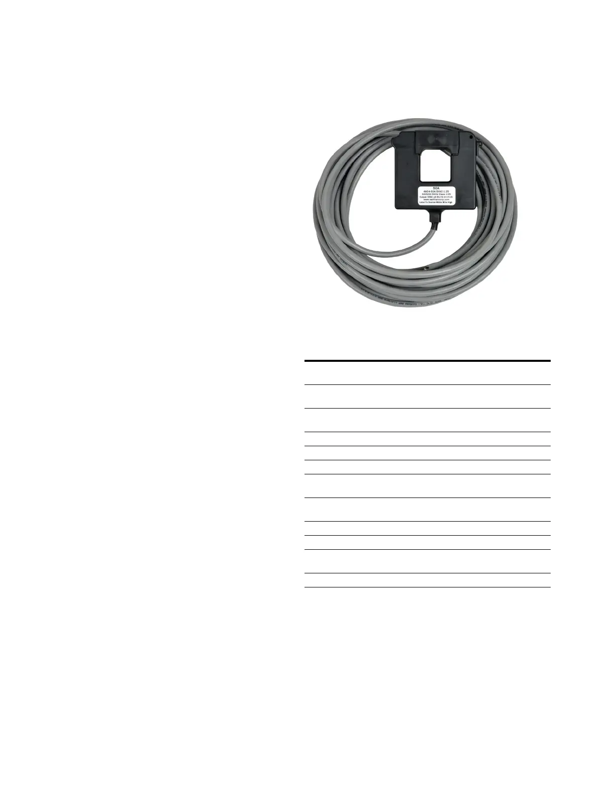
The CBC-NCSENSOR-35 sensor comes with a 35 foot
twisted-pair 18 AWG cable with pigtails. The cable may be
connected to the neutral current input of a junction box, or
routed to the meter base for socket mount controls.
Figure 42. CBC-NCSENSOR-35 neutral current sensor.
Table 9. Neutral current sensor specifications.
Spec Value
Size 3.8” W x 3.3” H x 1” D, 1.25" window
(9.65 cm W x 8.38 cm H x 2.54 cm D, 3.18 cm window)
Current Range 50 A ±1% over the range of 0.5 A to 50 A calibrated to
0.5% full
Over Current 100 A continuously will not harm the CT – no DC
allowed
Voltage Range 600 VAC tested using 2500 VAC for up to 1 minute
Bandwidth 10 Hz to 5000 Hz
Output Voltage 10 VAC at 100 A input
Output Limiting Set by internal resistor and windings – will saturate
without harm
Phase Displacement Approximately 1 degree leading or lagging the input
current
Power Factor Any load current power factor from 0.5 to 1.0 lead or lag
Temperature Range -50° F to 185° F (-46° C to 85° C)
Temperature
Response
Less than 0.05% from -4° F to 185° F
(-20° C to 85° C)
Input Sensor Ratio 10:1

 Loading...


