Installation procedure
22 CBC-8000 capacitor bank control installation and operation instructions MN916001EN—October 2018 Eaton.com
DIN connector options
Four DIN connector options are available for connecting
sensor inputs to the CBC-8000 control:
• 5-Pin DIN Connector (MS3102R16S-8P)
• 7-Pin DIN Connector (MS3102R16S-1P)
• 8-Pin DIN Connector (Sensor Inputs Only; MS3102R20-7P)
• 14-Pin DIN Connector (3-Phase Metering and Control;
MS3102R20-27P)
A DIN connector is required to use the CBC-8000 control’s
sensor control capabilities.
For information on Eaton’s Cooper Power series wiring
harness options, see
Wiring harness options on Page 24.
5-Pin DIN connector
The 5-pin DIN connector is a legacy option that only offers
trip, close, and power functionality. This DIN configuration
does not support sensor inputs, the full 3-phase
measurements sets, or any sensors. This DIN option is
equivalent to a four-jaw socket mount control.
To attain 3-phase functionality, this configuration may be
used in conjunction with the 8-pin DIN option.
The 5-pin DIN signal assignments are as follows:
Pin Signal
ALine
B Neutral/Common
CClose
D Trip/Open
E Not Used
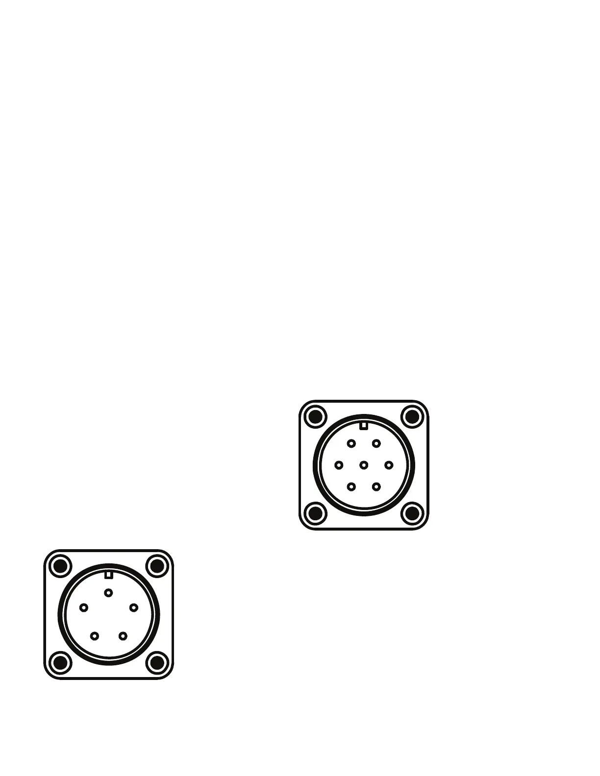
An example of the 5-pin DIN male connector with the pin
locations is shown in
Figure 22.
The CBC-CTRLCBL5P-40 wiring harness from Eaton’s
Cooper Power series is designed for use with the control’s 5-
pin DIN connector, see Wiring harness options on Page
24.
Figure 22. 5-pin male DIN connector.
7-Pin DIN connector
The 7-pin DIN connector is a legacy option that supports up
to two external sensors for var, current, or neutral current
measurements. This DIN option is equivalent to a six-jaw
socket mount control.
To attain 3-phase functionality, this configuration may be
used in conjunction with the 8-pin DIN option.
The 7-pin DIN signal assignments are as follows:
Pin Signal
ALine
B Trip/Open
CClose
D Sensor Return (Common)
E Neutral Current
F Line Current Sensor Hot/Sensor 1
G Neutral/Line 2
An example of the 7-pin DIN male connector with the pin
locations is shown in
Figure 23.
The CBC-CTRLCBL7P-40 wiring harness from Eaton’s
Cooper Power series is designed for use with the control’s 7-
pin DIN connector, see Wiring harness options on Page
24.
Figure 23. 7-pin male DIN connector.
A
B
C
D
E
F
G

 Loading...


