Communications
Communicate with the CL-6 control using ProView NXG
software or protocols such as DNP3 or 2179. The ProView
NXG software, used with a PC, can provide temporary local
connection to the control.
Communication ports
There are three physical communications ports on the CL-6
control.
The communication port Com1 is for use as a temporary
local communication connection to the control. Connection
is made to Com1 by using a standard 9-pin RS-232 cable to
the RS-232 DCE, female, 9-pin connector, located on the
front of the control. The port settings are configured at FC
60 through FC 67, FC 266 and FC 267. When using ProView
NXG software, modifications are not normally needed to
these settings.
The communication port Com2 is for use as a permanent
communication connection to the control. Connection is
made by using an optional communication accessory card
mounted on the back panel within the control enclosure
such as the Fiber Optic/RS-232 accessory. The port settings
are configured at FC 160 through FC 169, FC 268 and FC
269.
The communication port Com3 is for use as a secondary
permanent communication connection to the control. The
port shares its data source with the Com1 port and will be
inactive if a local connection is made to the Com1 port.
Com2 and Com3 may be active simultaneously and can be
communicating to two separate master stations. The set-
tings for this port are configured at FC 60 through 67.
There are two logical DNP3 addresses for each port.
Normally the port’s remote address 2 is used only by the
ProView NXG software for configuration. The port’s remote
address 1 is designed for interfacing with master stations. It
is possible to have two separate masters communicating to
the device through a single communication port.
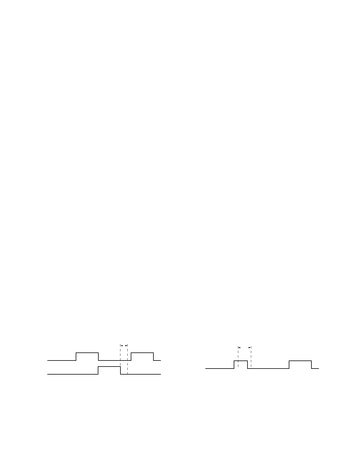
Depending upon the communication system into which the
control is being implemented, communication timing may
need to be modified. The sync time parameter defines a
period of time that the control must idle before recognizing
the start of a message. The amount of sync time may need
to be increased when the control is placed in a loop (ring)
configuration with more than three controls; refer to Figures
7-3 and 7-4.
Protocols
There are two protocols resident in the CL-6 control: 2179
and DNP3. While only one protocol can be selected for a
single Com port at a time, the two com ports can be set to
different protocols. Both of the protocols are highly
configurable.
The 2179 ordinal points map is selected at FC 266 and the
DNP3 data dictionary is selected at FC 267. By changing
from the default CL-6 control to either the CL-5E or CL-5D
control, the control will look just like a CL-5E or CL-5D
control to a master station. Therefore, the master does not
need to be upgraded unless some of the new functions, not
available in the older controls, need to be accessed through
remote communications.
A “USER” 2179 ordinal points map setting and a “USER”
DNP3 data dictionary setting are also available. These can
be configured via remote communications, including
ProView NXG software. This allows the user to create a map
to match other existing equipment or optimize for their
system as needed. DNP3-related parameters, including
Class configuration and deadbands, may also be configured
through communications.
Programmable input and output
Programmable Input and Output (Programmable I/O or PIO)
is a powerful tool since it provides the user with the means
to configure general logic equations. These logic equations
can be used to perform discrete SCADA functions, modify
control function, or add communications data points. PIO
can be configured via digital communications software,
including ProView NXG software. PIO configuration is
available via 2179 or DNP3 digital communications
protocols.
To configure PIO, the user first selects the output to be
performed. Then the logical form of the equation is chosen.
Standard AND, OR logical operators may be used in the
equation. A more advanced user may also choose to add
If-Then, If-Else, If-Else-If, and Timer-based conditional forms
within the programmable I/O feature. Lastly, the inputs to
the equation are chosen. A total of eighteen different logical
inputs may be included in one expression. The inputs or
outputs of the expression may be logically inverted.
Figure 7-4. Message received at CL-6 control;
message is not for the CL-6 control.
MESSAGE
MESSAGE
R
X
D RECEIVE
DATA
SYNC TIME
Figure 7-3. Message received at CL-6A control;
message is for the CL-6A control.
MESSAGE MESSAGE
R
X
D RECEIVE
DATA
SYNC TIME
T
X
D TRANSMIT
DATA
95
CL-6 SERIES CONTROL INSTALLATION, OPERATION, AND MAINTENANCE INSTRUCTIONS MN225016EN January 2016
 Loading...


