Auto-restore local (ARL)
Two additional functions that can be enabled at FC 450 are
Auto-Restore Local Heartbeat (ARLH) and Auto-Restore
Local Comms (ARLC). When SCADA communications are
being used to modify basic configuration settings, enabling
Auto-Restore Local will allow the control to revert control
settings modified through SCADA communications back
to the original settings programmed into the control. With
ARLH, the settings will revert when a heartbeat signal is
lost or discontinued. For ARLC, the settings will revert
when a communications signal is lost. The settings that are
affected by ARL are the same as those listed for Alternate
Configurations. When either ARL function is active, FC 451
will display Active.
For more information on setting up ARL with SCADA
communications, contact your Eaton representative.
Programmable input/output (P.I.O.)
Alternate Configurations settings can be enabled using P.I.O.
In order to enable Alternate configuration settings using
P.I.O., the Alternate Configuration setting (FC 450) must be
set to P.I.O. Equations must then be created using CCI soft-
ware which program the conditions under which Alternate
Configuration settings will become active. When Alternate
Configuration settings are active due to P.I.O. logic, the
status at FC 451 will display Active.
For more information on enabling Alternate Configuration
settings using P.I.O., contact your Eaton representative.
Transducer connections
Refer to Figure 10-4. To monitor the load voltage (forward
direction), a transducer, nominal 120 Vac input, may be
connected as follows: Connect the transducer hot lead
to terminal V
4
on TB
1
and its ground lead to G on TB
1
. A
current transducer, 200 mA input, may be connected as
follows: Close knife switch C; remove the jumper between
C
2
and C
4
on TB
1
; connect the transducer hot lead to C
2
and its ground lead to C
4
; and open knife switch C.
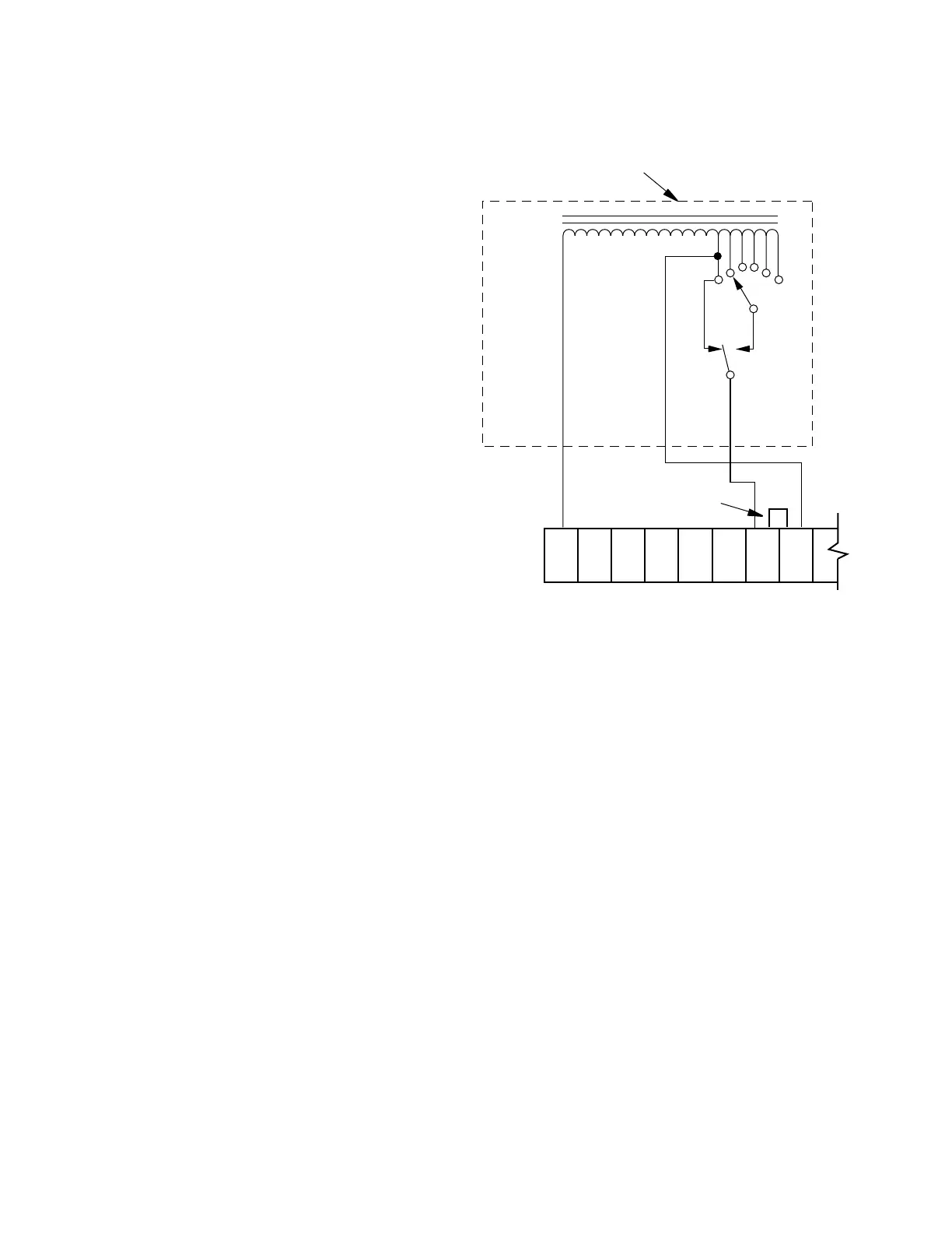
Fooler voltage scheme
Using this method, the voltage sensed by the control is
raised, thereby “fooling” the control into reducing the
voltage during its normal automatic operation. This method
can be used with the CL-6 Series controls. A VR module,
as shown in Figure 6-16, is usually supplied by the Remote
Terminal Unit (RTU) manufacturer. The VR module is usually
a tapped auto-transformer with a pulse-activated indexing
relay. When connected to the control back panel as shown,
the voltage sensed by the control is raised as the module is
pulsed to higher taps.
Since this method keeps the control in automatic operation,
Auto-Inhibiting is not used. An advantage of this method is
that it can be applied to many different models of controls
from many manufacturers. A disadvantage of this method
is that while VR is activated, the measured load voltage
is incorrect, as are all other calculated metering values
which use the load voltage. To avoid the effects of metering
inaccuracy, the Pulse Mode of VR should be used.
Figure 6-16. Typical user provided “Fooler
Voltage” module.
Common V(IN) V(OUT)
Relay
K
TB
1
G HS R
1
L
1
NL DHR V
S
V
5
Remove Jumper
User-provided Remote
Voltage Reduction Module
88
CL-6 SERIES CONTROL INSTALLATION, OPERATION, AND MAINTENANCE INSTRUCTIONS MN225016EN January 2016
 Loading...


