OPERATION: (Figure 6-3) Always operates in the reverse
direction using the reverse settings at FC 51, FC 52, FC
53, FC 54, and FC 55. This allows operation down to zero
current conditions since there is no reverse threshold
involved. A safeguard has been built into the control to
prevent misoperation in the event forward power flow does
occur. If more than 2% (.004 A CT secondary) forward
current occurs, the control idles on the last tap position held
and the band edge indicators will turn off. As the current
flow returns to a level above this forward threshold, normal
reverse operation resumes.
Figure 6-3. Locked reverse mode operation.
Reverse idle mode
When FC 56 is set for Reverse Idle, a source voltage is
required for metering only. This mode is recommended
for installation where reverse power flow may occur, but a
source voltage is not available.
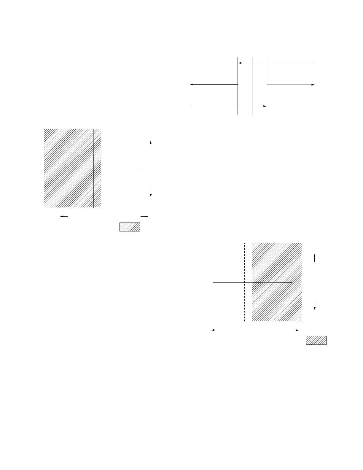
METERING: (Figure 6-4.) A threshold level of 1% (.002 A)
of the full load CT secondary current (.200 A) is used in
setting the power direction. The metering will be forward
until the current exceeds the 1% threshold in the reverse
direction. At this time, the various parameters use the
reverse settings and the Reverse Power indicator turns on.
The control continues metering in reverse until the current
exceeds the 1% threshold in the forward direction, and
then the parameter scaling reverts back to normal and the
Reverse Power indicator turns off.
OPERATION: (Figure 6-5.) The threshold for which the
control switches operation is programmable at FC 57 over
the range 1 to 5% of the rated CT current. When the real
component of the current is above this threshold, the
control operates in the normal forward direction. When
current falls below this threshold, all tap changing is
inhibited.
The control idles on the last tap position held before the
threshold was crossed. The operational timer (time delay) is
reset on any excursion below this threshold, and the band
edge indicators turn off.
Reactive Current
Real Current (% of C.T. Primary)
Reverse =
2%0
Figure 6-4. Reverse idle metering.
Normal Forward
Metering
Rev Pwr Off
Normal Metering
Forward Scaling
Rev Pwr On
Current Level
1% 0 1%
Figure 6-5. Reverse idle mode* operation.
Reactive Current
Real Current (% of C.T. Primary)
Forward Operation =
0
0T
OT=Operating Threshold, FC 57, 1-5%
Tap changing is inhibited
when real component of
current is at or below the
operation threshold, FC 57.
* Tap changing is inhibited and band edge indicators are turned off.
80
CL-6 SERIES CONTROL INSTALLATION, OPERATION, AND MAINTENANCE INSTRUCTIONS MN225016EN January 2016
 Loading...


