EXAMPLE 1:
•
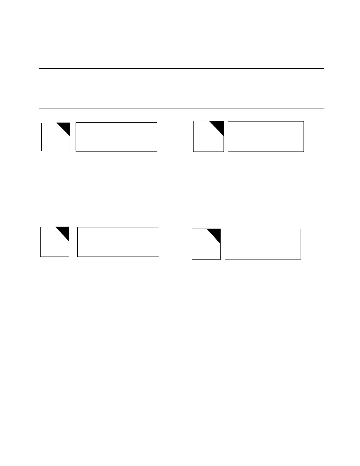
Load Current = 600 A
•
Forward Power Flow
•
Reverse Threshold Current = 12 A
•
Bi-directional operating mode
•
Voltage applied to Terminal 5, Terminal Block #8. (See
Remote Motor Control & Auto Inhibit.)
EXAMPLE 2:
•
Load Current = 200 A
•
Reverse Power Flow
•
Reverse Threshold Current = 2 A
•
Bi-directional operating mode
•
Automatic tapping is not inhibited
Tap position
When the *Tap Position key is pressed, the LCD will
display the following information:
The first line displays the present tap position. Neutral tap
position is represented as a "0". Tap positions lower than
zero are denoted with a negative sign; tap positions above
zero do not carry a sign.
The second line is used to indicate when the tap changer
has reached a Soft ADD-AMP limit or a user-configured
Position Indicator (P.I.) ADD-AMP limit. In Example 1, the
second line is blank because the tap changer is not at an
ADD-AMP limit.
If the Soft ADD-AMP feature is enabled, the third line is
used to display the corresponding Soft ADD-AMP limits.
The fourth line is used to display the physical P.I. ADD-AMP
settings corresponding to the physical position indicator.
Note: Physical ADD-AMP always takes precedence over soft.
EXAMPLE 1:
•
Present tap position = 8 Raise
•
Soft ADD-AMP feature = On
•
Soft ADD-AMP feature lower tap limit = -12
•
Soft ADD-AMP feature upper tap limit = 14
•
User-configured P. I. ADD-AMP lower tap limit = -14
•
User-configured P. I. ADD-AMP upper tap limit = 16
EXAMPLE 2:
•
Present tap position = 12 Lower
•
Tap Changer at ADD-AMP Limit
•
Soft ADD-AMP feature = On
•
Soft ADD-AMP feature lower tap limit = -12
•
Soft ADD-AMP feature upper tap limit = 14
•
User-configured external lower tap limit = -14
•
User-configured external upper tap limit = 16
TABLE 7-1 Blocking Condition Priority Levels
Load Current 600 Fwd
Current Threshold 12
Mode Bi-directional
Blocked: TB8-4&5
Tap Position 8
SOFT-ADD-AMP -12, 14
P.I. ADD-AMP -14, 16
4
Tap
Position
Load Current 200 Rev
Current Threshold 2
Mode Bi-directional
Tap Position -12
At Limit
SOFT-ADD-AMP -12, 14
P.I. ADD-AMP -14, 16
Level (1 = Highest) Automatic Blocking Condition LCD display text (line 4)
1
2
3
4
5
Control Function Switch is in Off or Manual position.
Tap-to-Neutral enabled.
Voltage applied to terminal 5, TB 8.
Blocked due to configuration setting found at FC 69.
Blocked due to reverse power flow mode.
Blocked:Cntrl Switch
Blocked:Tap-To-Neutr
Blocked: TB8-4&5
Blocked:Func Code 69
Blocked:Rev Pwr Mode
91
CL-6 SERIES CONTROL INSTALLATION, OPERATION, AND MAINTENANCE INSTRUCTIONS MN225016EN January 2016
 Loading...


