Cogeneration mode
When FC 56 is set for cogeneration, a source voltage is
required.
In recent years, there have been a growing number of
voltage regulator applications involving cogeneration by
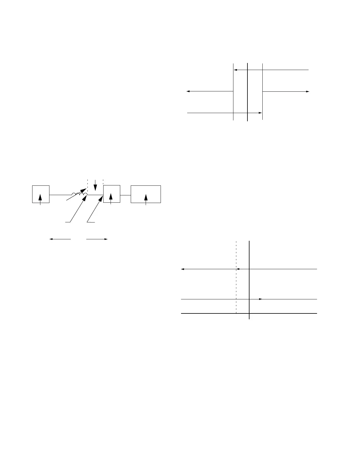
utility customers. The cogeneration mode was developed
for the Cooper regulator control to satisfy the specialized
needs of these applications. Normally, the desired operation
of a regulator installed on a feeder involving cogeneration
is to regulate the voltage at the customer substation during
times of power flow into the customer site and to regulate
the voltage at the regulator (on the same output side) during
power flow into the utility grid. This is accomplished by
simply not reversing the control sensing input voltage when
reverse power is detected and by altering the line-drop
compensation settings to account for this change in power
flow direction. (See Figure 6-9.)
Figure 6-9. Cogeneration regulation points.
METERING: (Figure 6-10.) Always operates in the forward
direction except that load center voltage is calculated based
upon the reverse line-drop compensation settings (FC 54
and FC 55) when the fixed 1% reverse metering threshold
is exceeded. The Reverse Power indicator turns on when
this reverse threshold is crossed. The forward line-drop
compensation settings (FC 4 and FC 5) are used when the
current exceeds the fixed 1% forward metering threshold.
The demand values acquired during reverse power flow
are stored as reverse metered data, but the values are not
scaled (to reflect the other side of the regulator) since the
operating direction of the regulator never truly reverses.
OPERATION: (Figure 6-11.) The control always operates in
the forward direction. The control will operate in the forward
direction, but will use the reverse settings for line-drop
compensation when the real component of the current is
above the fixed 1% reverse metering threshold. The control
will continue to use the reverse line-drop compensation
settings until the real component of the current is above the
fixed 1% forward metering threshold. The operational timer
(time delay) is not reset on any transitions between the
application of forward and reverse line drop compensation
settings.
Line-Drop
Compensation
Difference
Regulated
Voltage during
Forward Power Flow
Regulated
Voltage during
Reverse Power Flow
Utility
Substation
Cogeneration
Site
Customer
Substation
Stiff
Bus
Figure 6-10. Cogeneration metering.
Normal Forward
Metering
Rev Pwr Off
Reverse Metering
with Reverse LDC
Rev Pwr On
Current Level
1% 0 1%
Reverse
Forward
Figure 6-11. Cogeneration mode operation.
-5 -4 -3 -2 -1 0 1 2 3 4 5
Reverse LDC @ -1%
Forward LDC @ +1%
Forward Operations
with Forward LDC
Percent of C.T. Rating
Reverse Operations
with Reverse LDC
82
CL-6 SERIES CONTROL INSTALLATION, OPERATION, AND MAINTENANCE INSTRUCTIONS MN225016EN January 2016
 Loading...


