M3 Vital Signs Monitor Service Manual
- 16 -
Voltage Detection Circuit
Detects the output voltage of every part in detection circuit, converts analogue signals to digital
signals and then send them to Main control board for processing.
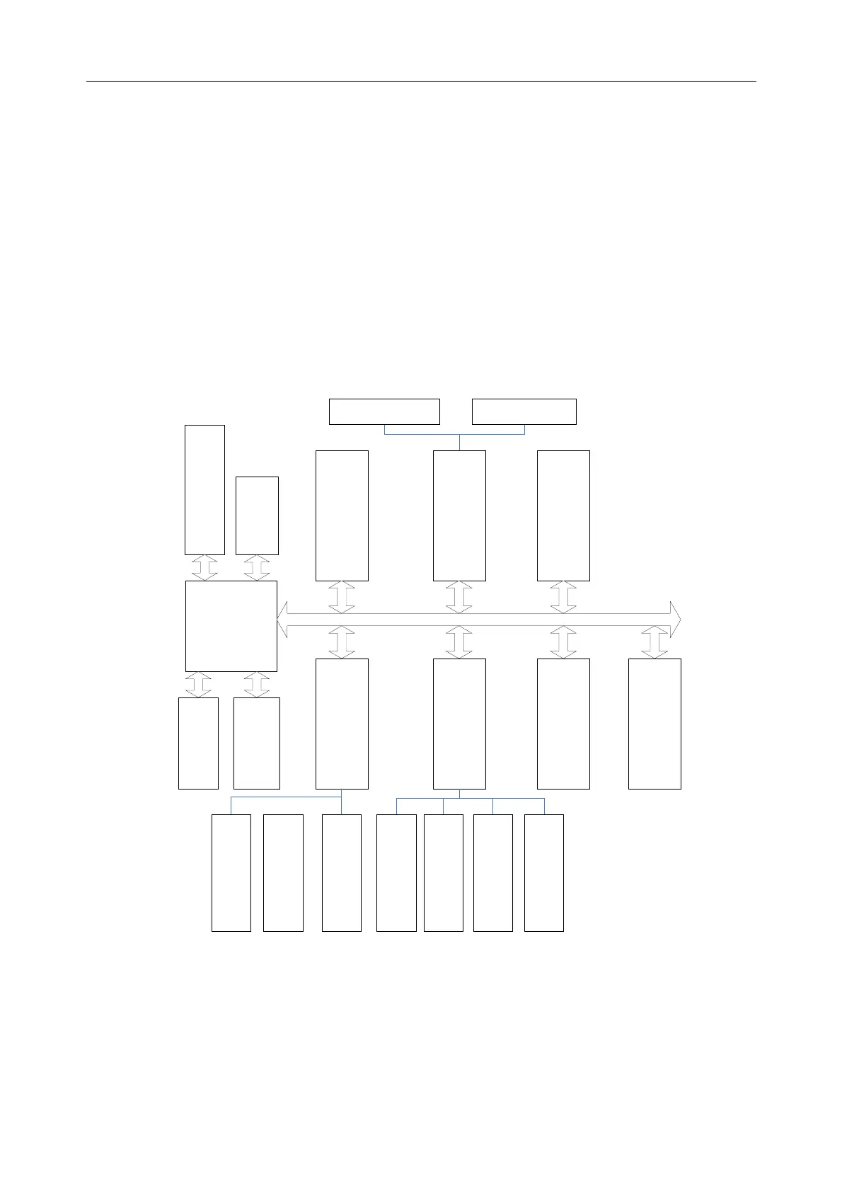
2.2.2 Main Control Board
Main control board which is consisted of Interface board and Core board, is the heart of monitor,
it can do system control, system adapter, system management, data processing, file management,
display processing, recorder management, data storage, system diagnosis, fault alarm, etc.
Main control board schematic diagram
Figure2-4 Schematic Diagram of Main Control Board
CPU System
CPU is the kernel of ARM9, it is the core part of the Main control board. CPU connects with other
periphery modules by bus and I/O cable, it can realize data communication, data processing,
ARM9
CPU
Stabilized power
Watchdog
COM3
COM4
COM5
COM6
COM7
COM8
Serial port
slave chip2
Serial port
slave chip
Printer port
Data bus
PS/2 keyboard
I/O port
Network driver
Audio driver
TFT/VGA driver
FLASH
CPLD driver
USB port
Serial port
0-2
 Loading...