M3 Vital Signs Monitor Service Manual
- 28 -
5 Disassembly Graph
This chapter introduces the inner structure and parts of the monitor, including disassembly graph,
front shuck assembly, rear shuck assembly and main bracket assembly.
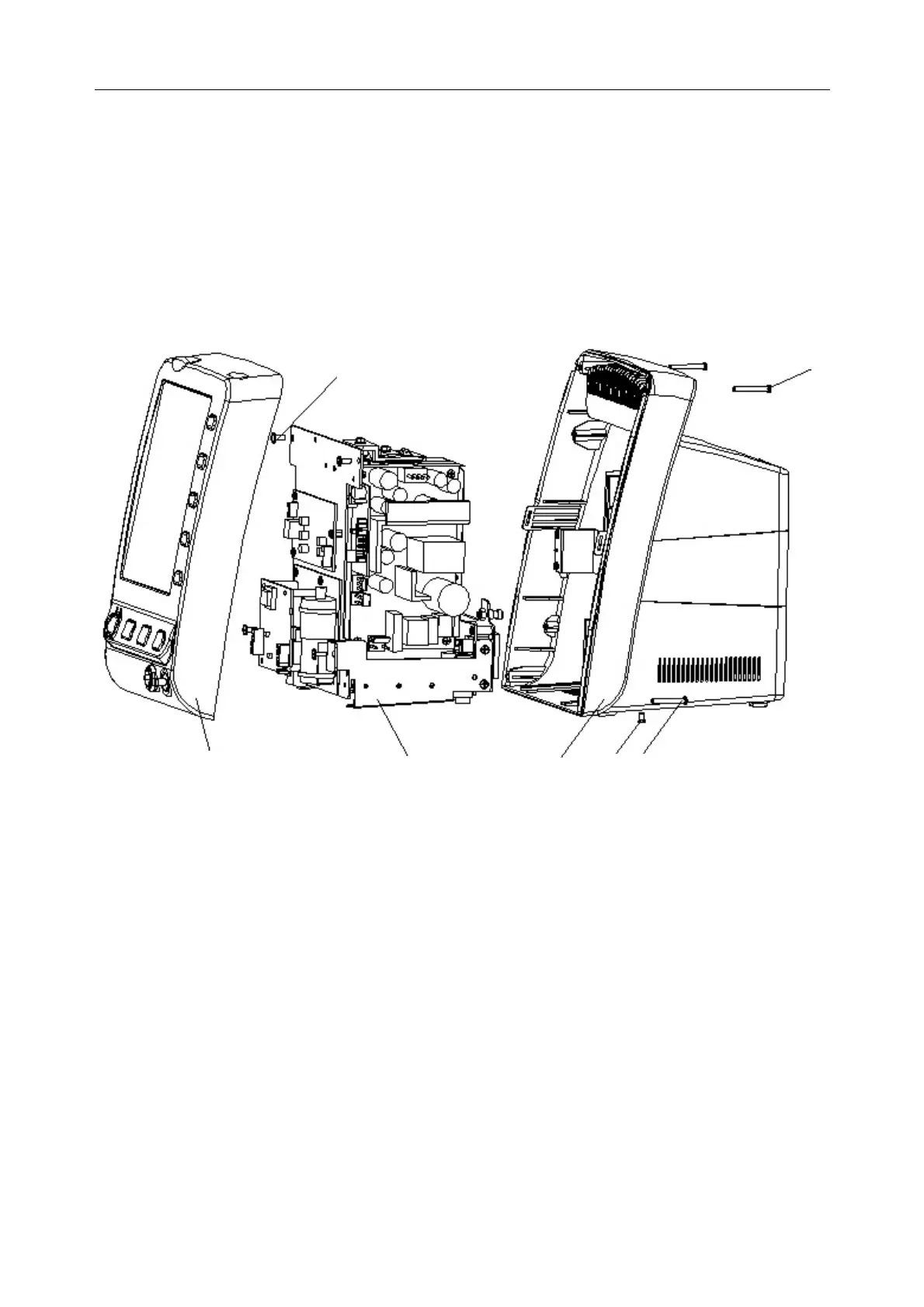
5.1 Disassembly Graph
1: M3 Front shuck assembly; 2: Main bracket assembly; 3: M3 rear shuck assembly; 4:
Cross recessed countersunk head screw M3×6; 5, 7: Cross recessed round head screw
M3×25; 6: Cross recessed pan head coil spring screw.
Figure5-1 Monitor disassembly, exploded
5.2 Front Shuck Assembly
2
1
3
4
5
6
7
 Loading...