© Edwards Limited 2013. All rights reserved. Page 27
Edwards and the Edwards logo are trademarks of Edwards Limited.
Installation
B722-40-880 Issue F
4. To monitor the Fail status output, connect the customer control equipment to the Fail output (pin 7) and to pin
2 of the logic interface mating half. The output can be used to control other devices in the pumping system. The
output can drive a low power relay of up to 24 V coil rating.
3.7 Serial interface mode
The Serial Interface can be used to control the DX pump and to interrogate its operational status using a number of
commands. There is a multi-drop mode that allows for communication with more than one DX pump whilst using just
one control system.
3.7.1 Connect the serial interface to the customer control equipment
When connecting the DX pump to a PC, remember that the 0 V pin on the RS232 connector may well be
connected to earth through the PC. If this is the case, ensure that the 0 V rail of the 24 V supply is not also
connected to earth at some other point such as at the power supply. If the 0 V rail of the 24 V supply will not
be connected to earth at the PC, an opto-isolated interface to the PC should be used.
The DX pump can connect directly to the RS232 serial input on a PC as shown in Figure 9. In this configuration, the
PC is the serial link master and the DX pump is the slave. The distance over which the serial link will work is
dependent on any difference in voltage between the 0 V at the sending and receiving end. If the 0 V reference at the
receiving end is within 0.3 V of the 0 V Control Reference pin on the DX pump control connector then the serial link
should be capable of operating at distances up to 6 m. An interface circuit external to the DX pump may be required
for longer distances.
The software in the DX pump is capable of operating with several pumps connected to a single serial link master. This
is referred to as multi-drop mode. However, the serial interface driver in the DX pump is based on the RS232
standard, which is only intended for point to point serial links. Some additional hardware will be required to link
several DX pump units to a single serial link master. A concept drawing of one possible arrangement is shown in
Figure 10.
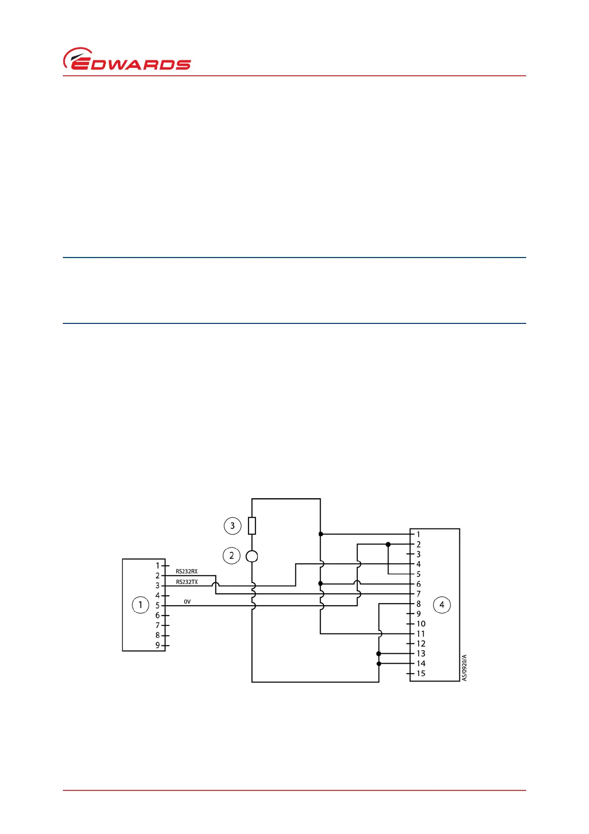
Figure 9 - Logic interface connections - serial mode
1. RS232 interface on control equipments
2. 24 V d.c. electrical supply
3. Fuse
4. DX pump logic interface

 Loading...