© Edwards Limited 2013. All rights reserved. Page 35
Edwards and the Edwards logo are trademarks of Edwards Limited.
Installation
B722-40-880 Issue F
are wired correctly, follow the electrical connection instructions given in the Accessories Manual (supplied with the
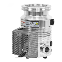
TAV valve) and refer to Figure 4 and Section 2.9. Plug the connector into the socket at the top of the Podule (refer
to Figure 1 and 2, items 1 and 7 respectively).
The Podule is capable of controlling a number of different venting options, these are defined in Table 18.
When the pump is shipped, the Podule is configured with the factory default vent option 0, as detailed in Table 18.
The Podule can be configured to another venting option, provided commands can be sent via the Serial Interface or
an Edwards TIC Turbo and Instrument Controller or Turbo Controller.
The Podule only energises (‘shuts’) the TAV solenoid valve when it receives a Start command. Prior to that, the valve
will be in the ‘open’ vent state. If the vacuum system is a large system, allow the backing pump to reduce the
pressure in the system to an acceptable level before starting the DX pump. In this case, send a command via the
Serial Interface to close the vent valve before sending a Start command. This is known as a delayed start.
If the DX pump is controlled with an Edwards TIC Turbo and Instrument Controller or TIC Turbo Controller, the TAV
solenoid valve can be driven from the TIC. Refer to the TIC Instruction Manuals for more information.
3.8.4 Alternative valve connected to the vacuum system
If using another vent valve, ensure that a suitable vent restrictor is fitted to the vacuum system to limit the rate of
pressure rise. Refer to Table 19 for information about vent restrictor sizes. If a suitable vent restrictor is not fitted,
open the vent valve only after the speed of the pump has fallen to 50% of full rotational speed.
Table 18 - Vent options
Option number Description of vent function
0 Vent valve opens fully below 50% full rotational speed for either Stop command or
Fail.
Note: This is the factory default setting.
1 Controlled venting from 100% to 50% full rotational speed; vent valve opens fully
below 50% for either Stop command or Fail.
2 Vent valve fully opens immediately Stop command is received; vent valve opens
fully below 50% full rotational speed if Fail.
3 Vent valve fully opens immediately Stop command is received; controlled venting
from 100% to 50% full rotational speed if Fail then vent valve opens fully below
50%.
4 Vent valve fully opens immediately if Fail; vent valve opens fully below 50% full
rotational speed if Stop.
5 Vent valve fully opens immediately if Fail; controlled venting from 100% to 50% full
rotational speed if Stop command received then vent valve opens fully below 50%.
6.7 Vent valve fully opens immediately for either Stop command or Fail.
Table 19 - Vent restrictor orifice diameter (with atmospheric pressure at the inlet of the vent valve)
Vacuum system volume (litres) Orifice diameter (mm)
<20 1.0
<10 0.7
<5 0.5
<2 0.35

 Loading...