Installation
MGE-205 and 208 Mounting Dimensions Inches (mm)
AG
A
BC Aid
11 Max XD
S Min
ft
C Max AJ
BB
AK
BF
205
5.60
2.25 .46 1.20 .375 .563 1.27
.563
2.0
2.625
.063
1.502 .205
(143.0)
(57.2) (11.2)
(30.5)
(9.525)
(14.3)
(323) (14.30) (2.00)
(66.69)
(1.60)
(38.15
(5.21)
208
6.75
2.25 .46 1.20 .375 .563 1.27 563
2.0
2.625
.063
1.502
.205
(171.4)
(57.2) (11.2)
(30.5)
(9.525) (14.3)
(3.23)
(1430)
(2.00)
(66.68)
0.60)
(38.15)
(5.21)
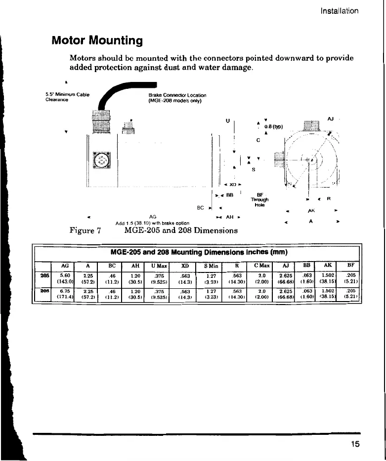
Motor Mounting
Motors should be mounted with the connectors pointed downward to provide
added protection against dust and water damage.
5.5' Minimum Cable
Clearance
Brake Connector Location
(MGE-208 models only)
BC
BI3
• AG >t AH
Add 1 5 (38.10) with brake option
Figure 7 MGE-205 and 208 Dimensions
BF -
Dm:ugh a; •
Hole
AK
A
15
 Loading...