EN Series Drives Manual
351
lnpu' M4
Input
Input
out #
Output p3
Outp,`
Outpt.•
/0 Con .opt
/C Corr,o1 —
t/0 Supply +
Supply
EN Drive
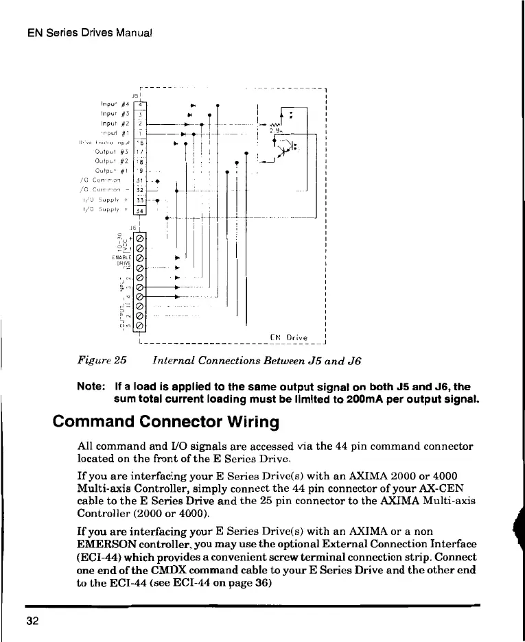
Figure 25 Internal Connections Between J5 and J6
Note: If a load is applied to the same output signal on both J5 and J6, the
sum total current loading must be limited to 200mA per output signal.
Command Connector Wiring
All command and I/O signals are accessed via the 44 pin command connector
located on the front of the E Series Drive.
If you are interfacing your E Series Drive(s) with an AXIMA 2000 or 4000
Multi-axis Controller, simply connect the 44 pin connector of your AX-CEN
cable to the E Series Drive and the 25 pin connector to the AXIMA Multi-axis
Controller (2000 or 4000).
If you are interfacing your E Series Drive(s) with an AXIMA or a non
EMERSON controller, you may use the optional External Connection Interface
(ECI-44) which provides a convenient screw terminal connection strip. Connect
one end of the CMDX command cable to your E Series Drive and the other end
to the ECI-44 (see ECI-44 on page 36)
32
 Loading...