Installation
Brake Wiring
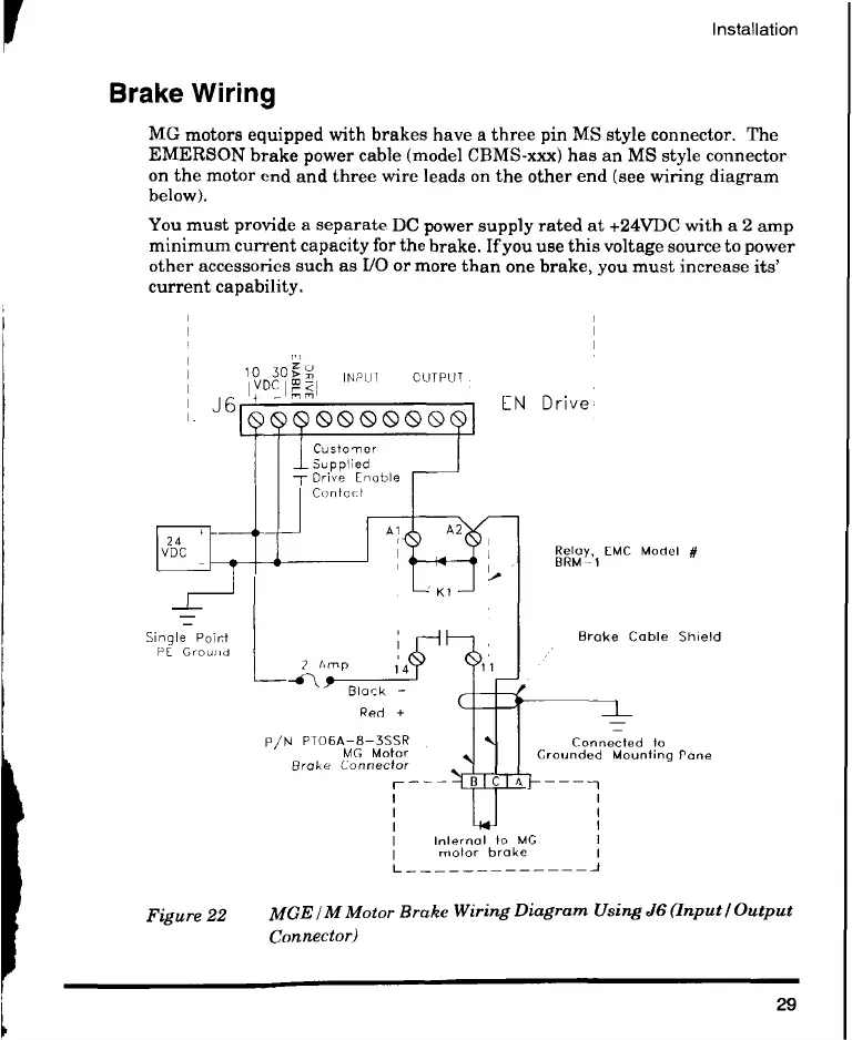
MG motors equipped with brakes have a three pin MS style connector. The
EMERSON brake power cable (model CBMS-xxx) has an MS style connector
on the motor end and three wire leads on the other end (see wiring diagram
below).
You must provide a separate DC power supply rated at +24VDC with a 2 amp
minimum current capacity for the brake. If you use this voltage source to power
other accessories such as I/O or more than one brake, you must increase its'
current capability.
10 30n n
VDCmmi
J6 EN Drive,
Single Point
PE Ground
INPUT OUTPUT.
Customer
Supplied
Drive [noble
Contact
Relay, [MC Model #
BRM-1
Brake Cable Shield
Black —
Red +
P/N P TO6A-8-3SSR Connected to
MG Motor Grounded Mounting Pane
Brake Connector
1 l
Internal to MG
motor brake
Figure 22 MGE / M Motor Brake Wiring Diagram Using J6 (Input I Output
Connector)
29
 Loading...