EN Series Drives Manual
Motor Feedback Wiring
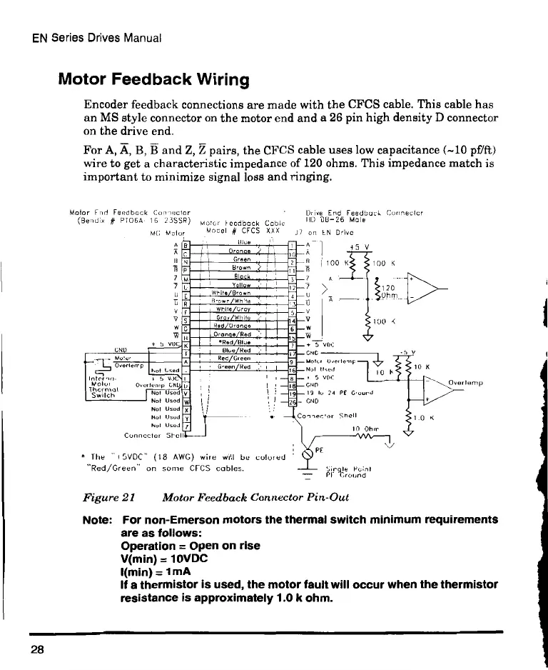
Encoder feedback connections are made with the CFCS cable. This cable has
an MS style connector on the motor end and a 26 pin high density D connector
on the drive end.
For A, A, B, B and Z, Z pairs, the CFCS cable uses low capacitance (-10 pf/ft)
wire to get a characteristic impedance of 120 ohms. This impedance match is
important to minimize signal loss and ringing.
Motor Frol Feedback Con -recto
(Bendix PT066 16 23566
6919
MG Motor
DOve End Feedbock Connecter
Motor h oedbock Coble IID 013-26 Mole
Motel # CFCS XXX J7 an EN Drive
A , 1310A 0
IMINIMMNIMMIM
0MIIMEIMIMPRIIIMU
0.11.=IIMIIIIEMI
7 MMIIMMIEMMU
illEM:MMEMEMMil
oMMONSU
—w bilm.2mtlirilirriMIRMI.10rani e Red TA
uMMill
ME=DEMEZ=MEMEMP
Mill1 emmalo
i
I
19
I 3.
L
VI
Not Used
Not Used
Not Used
Not Used
Not Used
Connector Stel
The -15VDC" (18 AWG) wire will be colored
"Red/Green- on some CFCS cables.
A .45 V
A Tl
Ta
ll
V
100 KS 5100 K
s 5 006
^NC
Mot, 0 e to K
Not IIt
S VOA
con
19 10 29 PE Gourd
CND
Connector Shell
10 Oh
0
P.
77 01,7e onv
120
PPrn
o
10 P
10 K
N./
1_0 K
Over lento
Figure 21 Motor Feedback Connector Pin-Out
Note: For non-Emerson motors the thermal switch minimum requirements
are as follows:
Operation = Open on rise
V(min) = 10VDC
I(min) = 1 mA
If a thermistor is used, the motor fault will occur when the thermistor
resistance is approximately 1.0 k ohm.
28
 Loading...