Installation
Input/Output And Drive Enable Wiring
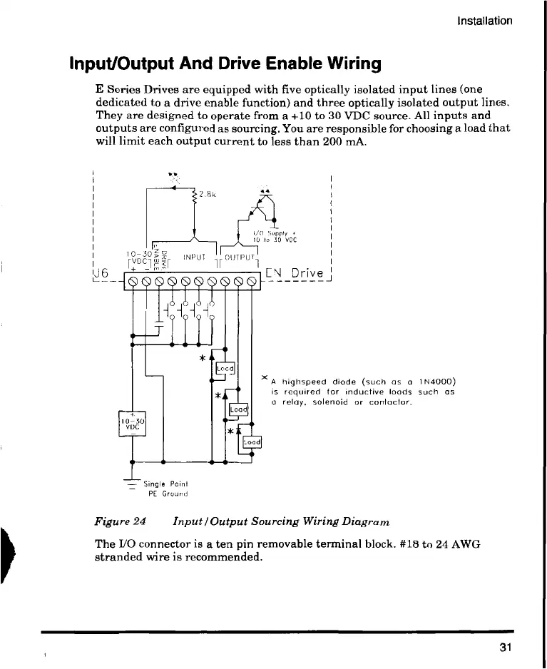
E Series Drives are equipped with five optically isolated input lines (one
dedicated to a drive enable function) and three optically isolated output lines.
They are designed to operate from a +10 to 30 VDC source. All inputs and
outputs are configured as sourcing. You are responsible for choosing a load that
will limit each output current to less than 200 mA.
vir
L6
2.Tik
10-30 INPUT
1--VF
Single Point
PE Ground
10 to 30 VDC
OUTPUT]
EN Drive J
A highspeed diode (such as a 1N4000)
is required for inductive loads such as
a relay, solenoid or contactor.
Figure 24 Input/Output Sourcing Wiring Diagram
The 1/0 connector is a ten pin removable terminal block. #18 to 24 AWG
stranded wire is recommended.
31
 Loading...