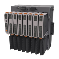
FB3000 RTU Instruction Manual
D301851X012
November 2023
94 Index
E
Ethernet
communications ............................................. 72
connecting ....................................................... 39
ports ................................................................. 39
Extension chassis ................................................ 12
DIN rail mounting ........................................... 18
F
FBxConnect ........................................................ 4, 6
FBxDesigner........................................................... 7
Features ................................................................. 2
Figures
1-1. FB3000 RTU ................................................ 1
1-2. Chassis – 8 Slot Version ............................ 3
2-1. FB3000 Dimensions – 8 Slot ................... 10
2-2. FB3000 Dimensions – 4 slot ................... 11
2-3. Removing Chassis Connector Cover ..... 13
2-4. Pressing Chassis Together ..................... 13
2-5. Chassis Ground Lug Location ................ 15
2-6. Isolated Ground Terminal Locations
(Highlighted in Red) ..................................... 16
2-7. Loop Power Ground Terminal Location 17
2-8. Chassis Mounting .................................... 18
2-9. Locations for Installing DIN Rail Clamps
at each end of Chassis Assembly ................ 18
2-10. Single 4-Slot Chassis only can be
Mounted Horizontally or Verticallyd .......... 19
2-11. Panel or Wall Mounting Screw Locations
........................................................................ 20
2-12. Sliding Off the Mounting Plate ............ 20
2-13. Screw holes – from Back (8-slot chassis)
........................................................................ 21
2-14. Figure Name .......................................... 22
2-15. Battery Saver Tab .................................. 22
2-16. External Power Connections ................ 23
2-17. External Power Connections ................ 24
2-18. Removing the I/O Cover ....................... 27
2-19. Configuring a Port in FBxConnect ....... 29
2-20. Wiring COM1 on the CPU Module for
RS-232 ............................................................ 29
2-21. Wiring COM1 on the CPU Module for
RS-485 (4-wire) .............................................. 30
2-22. Wiring COM1 on the CPU Module for
RS-485 (2-wire) .............................................. 31
2-23. Wiring COM2 on the CPU Module for
RS-232 ............................................................ 32
2-24. Wiring COM2 on the CPU Module for
RS-485 (4-wire) .............................................. 33
2-25. Wiring COM2 on the CPU Module for
RS-485
(2-wire) .............................................. 34
2-26. Wiring COM3 on the CPU Module for
RS-485 (2-wire) .............................................. 35
2-27. Wiring COM3 on the CPU Module for
RS-485(2 wire) ............................................... 36
2-28. Wiring COM4 on the CPU Module for
RS-485 (2-wire) .............................................. 37
2-29. Wiring COM4 on the CPU Module for
RS-485 (2-wire) .............................................. 38
2-30. Location of Ethernet Ports and Micro
USB Port on CPU .......................................... 39
2-31. COMn Port Configured for RS-232 ...... 41
2-32. COMn Configured for RS-485 (4-wire) 42
2-33. COMn Configured for RS-485 (2-wire) 43
2-34. COMn Configured for RS-485 (2-wire)
Connection to a Single Rosemount 4088B
Transmitter ................................................... 44
2-35. COMn RS-485 (2-wire) Connection to
Multiple 4088B Transmitters (Multi-Drop) 45
3-1. Analog Input (AI) Wiring ........................ 49
3-2. Analog Input (AI) Wiring ........................ 50
3-3. Analog Output (AO) Wiring .................... 51
3-4. Digital Input (DI) Wiring ......................... 53
3-5. Digital Output (DO) Wiring .................... 55
3-6. Digital Output (DO) Wiring .................... 56
3-7. Digital Output (DO) Wiring – Dry Contact
Closure .......................................................... 57
3-8. Digital Output (DO) Wiring – Contact
Closure using 24V Loop Supply .................. 58
3-9. Pulse Input (PI) Wiring ........................... 59
3-10. HART Wiring – Point-to-Point Mode ... 61
3-11. HART Wiring – Point-to-Point Mode-
External Supply ............................................. 61
3-12. HART Wiring – Multi-Drop Mode on
Channel 1 ...................................................... 62
3-13. HART Wiring – Multi-Drop Mode-
External Supply ............................................. 63
3-14. HART Comm Disabled – Channel Wired
as AI ............................................................... 64
3-15. HART Comm Disabled – Channel Wired
as AO ............................................................. 65
3-16. Analog Output (AO) Wiring .................. 68
3-17. Digital Output (DO) Wiring .................. 70
5-1. FB3000 RTU Components ...................... 76

 Loading...


