FB3000 RTU Instruction Manual
D301851X012
November 2023
16 Installation
Run the ground wire so that any routing bend in the cable has a minimum radius of 30.48
cm (12 inches) below ground and 20.32 cm (8 inches) above ground.
Note
If your installation includes multiple chassis, you must individually ground each chassis.
For more information on grounding or if your installation uses cathodic protection, refer
to Site Considerations for Equipment Installation, Grounding, and Wiring (D301452X012).
2.5.2 Internal System Bus Ground
The internal system bus ground provides an internal reference to system power negative
or ground input. Users cannot access this ground.
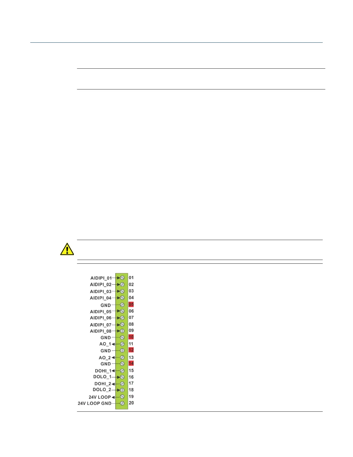
2.5.3 Isolated Ground on 3MIX12/3MSG12 Module
The 12-channel mixed I/O module includes an isolated ground system (ISO_GND) on pins
5, 10, 12, and 14 of TB1. ISO_GND provides a low noise return (ground) for analog inputs
and outputs. It is completely isolated from the other three ground systems. You can
optionally enable grounding for one or both digital outputs on the 12-channel mixed I/O
module through individual settings for each DO in FBxConnect. When enabled, digital
output(s) are internally connected to ISO_GND.
Important
When ISO_GND is enabled, DO maximum current is reduced from 500 mA to 50 mA.
Figure 2-6. Isolated Ground Terminal Locations (Highlighted in Red)
 Loading...