FB3000 RTU Instruction Manual
D301851X012
November 2023
18 Installation
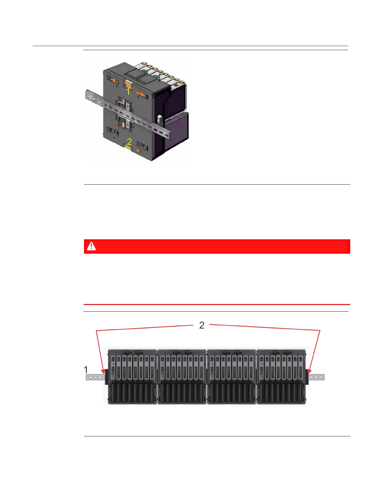
Figure 2-8. Chassis Mounting
Upper tab; retracts DIN rail clips
Lower tab; extends DIN rail clips so they snap back into place
If
the RTU includes one or more extension chassis on the DIN rail, ensure all chassis are
pressed together tightly so that side connectors between chassis are fully engaged.
Install DIN-rail clamps/brackets at both ends of the assembly to ensure side connectors
remain fully engaged.
EXPLOSION HAZARD - MAY CAUSE DEATH
When installing in a hazardous location, the installer must ensure the side connectors
between the chassis are fully engaged.
Failure to do so may result in death or serious injury to personnel.
Figure 2-9. Locations for Installing DIN Rail Clamps at each end of Chassis Assembly
Locations to install clamps/brackets (not shown) on DIN rail to hold chassis tightly
together and ensure side connectors between chassis remain fully engaged.

 Loading...