FB3000 RTU Instruction Manual
D301851X012
November 2023
I/O Configuration and Wiring 51
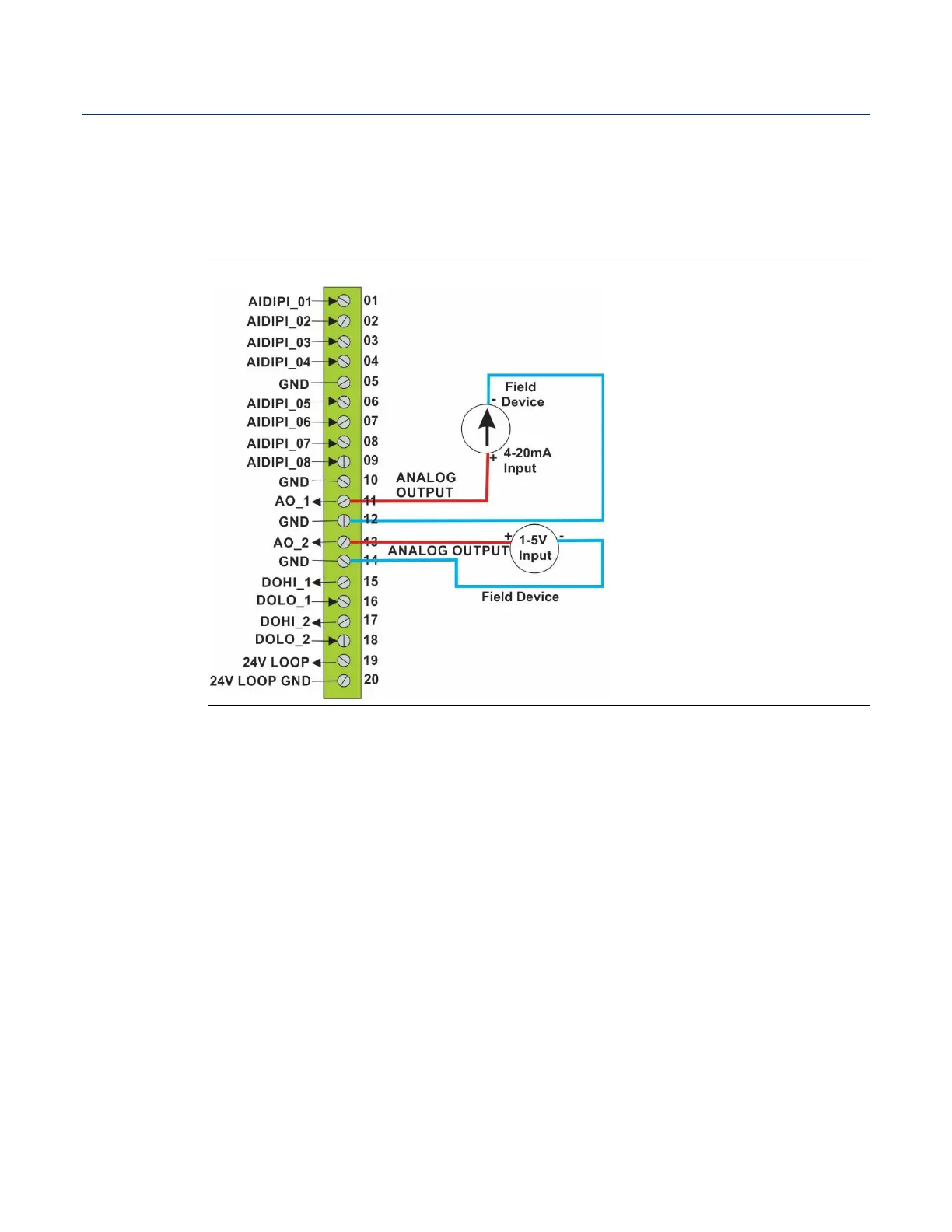
Figure 3-3 shows how to wire the analog output. In the figure, AO_1 is configured for
current output mode and is shown connected to an external current field device. AO_2 is
configured for voltage output mode and is shown connected to an external voltage field
device. AO_1 connects to the common ISO_GND using pin 12; AO_2 connects to the
common ISO_GND using pin 14.
Figure 3-3. Analog Output (AO) Wiring
Both AO channels are read back to check the health of the AO:
Current outputs with loads are verified to be within the operating range of the output.
Voltage outputs are verified to be within 10% of programmed values.
The firmware reports an open on a current output as an overrange AO.
The firmware reports a short on either a current or voltage output as an under-range
output.
The actual values read back are unavailable to the user and these checks are made
internal to the firmware.

 Loading...