DVC6000f Series
March 2006
6-6
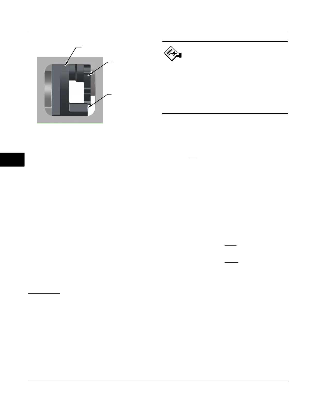
Figure 6-3. Shroud Opening Showing Rough Alignment of
Adjustment Disc
BEAM ASSEMBLY
ADJUSTMENT DISC
TRAVEL STOP
W8311
proper operation. First verify that these settings are
correct:
a. Relay Type − “B”
b. Travel Sensor Motion – “Clockwise or
Counterclockwise”
What direction does the potentiometer shaft rotate on
decreasing Output Pressure B)?
c. Zero Power Condition – “Open or Closed”
When the instrument electrical power is removed
(Output Pressure B at full supply), what is the valve
position?
2. Rough Relay Adjustment Check
Visually examine the location of the adjustment disc in
relation to the end of the travel stop on the beam
assembly. You can view the adjustment disc through
the opening in the metal shroud. It should be located
approximately
as shown in figure 6-3. If it is not in the
position shown, rotate the adjustment disc until the
correct position is attained.
Note
This is just a rough adjustment to
position the adjustment disc in the
correct range. Unless the disc has
substantially deviated from this
position, you do not need to make any
adjustments. If you are unsure,
continue on without making any
adjustments.
3. Obtain Control Valve Mid-Travel
Make sure the transducer block mode is Manual and
that there is supply pressure to the instrument. Follow
the Field Communicator prompts to position the valve
at mid-travel. (The important thing is to make sure that
Output B is not
fully saturated with full air supply or
fully vented with no air supply.) If mid-travel cannot be
obtained, perform the Travel Calibration routine to
roughly calibrate the instrument. If the instrument will
not calibrate, return to step 1.
4. Balance the Beam
Visually examine the travel stops on the beam
assembly with respect to the relay body. The gap
between the travel stops and the relay body should be
equal on both sides of the beam assembly (figures 6-4
and 6-5). If the gap is not equal, rotate the adjustment
disc as follows:
Rotate the adjustment disc in the “+” direction to
move the lower travel stop away
from the relay body.
Rotate the adjustment disc in the “−“ direction to
move the lower travel stop closer
to the relay body.
5. Proper Calibration
When both travel stops are equidistant from the relay
body, the reverse acting relay is properly calibrated.
The nominal clearance on each side should be 0.14
mm (0.055 inches). Perform a final Travel Calibration
routine.
6

 Loading...


