Calibration
March 2006
6-7
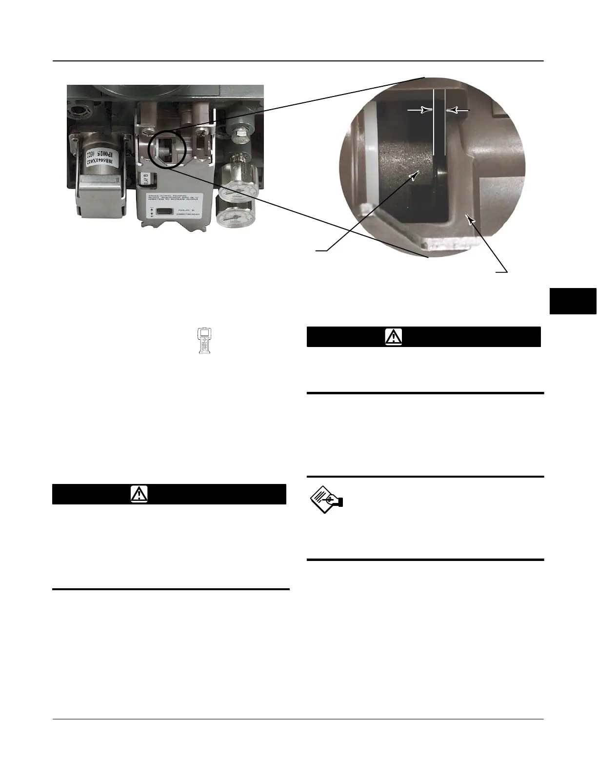
Figure 6-4. Relay Beam, Upper View
RELAY BODY
TRAVEL STOP
0.14 mm
(0.055 INCH)
W8277
Travel Sensor Adjust
(TB > Calibrate > Travel Sensor Adjust)
The travel sensor is normally adjusted at the factory
and should not require adjustment. However, if the
travel sensor has been replaced, adjust the travel
sensor by performing the appropriate procedure. See
the Maintenance section for Travel Sensor
Replacement procedures.
WARNING
During a travel sensor adjustment, the
valve may move. To avoid personal
injury and property damage caused
by the release of pressure or process
fluid, provide some temporary means
of control for the process.
DVC6010f, DVC6015, DVC6030f and
DVC6035 Digital Valve Controllers
1. Remove supply air and remove the instrument from
the actuator.
WARNING
Failure to remove air pressure may
cause personal injury or property
damage from bursting parts.
2. As shown in figure 6-6, align the feedback arm (key
79) with the housing by inserting the alignment pin
(key 46) through the hole marked “A” on the feedback
arm. Fully engage the alignment pin into the tapped
hole in the housing.
Note
The alignment pin (key 46) is
stored inside the digital valve
controller housing.
3. Loosen the screw that secures the feedback arm to
the travel sensor shaft. Position the feedback arm so
that the surface of the feedback arm is flush with the
end of the travel sensor shaft.
4. Connect a Fieldbus power source and the Field
Communicator to the instrument LOOP − and LOOP +
terminals.
5. Before beginning the travel sensor adjustment, set
the Transducer Block Mode to Manual and the
protection to None.
6

 Loading...


