Installation
March 2006
2-23
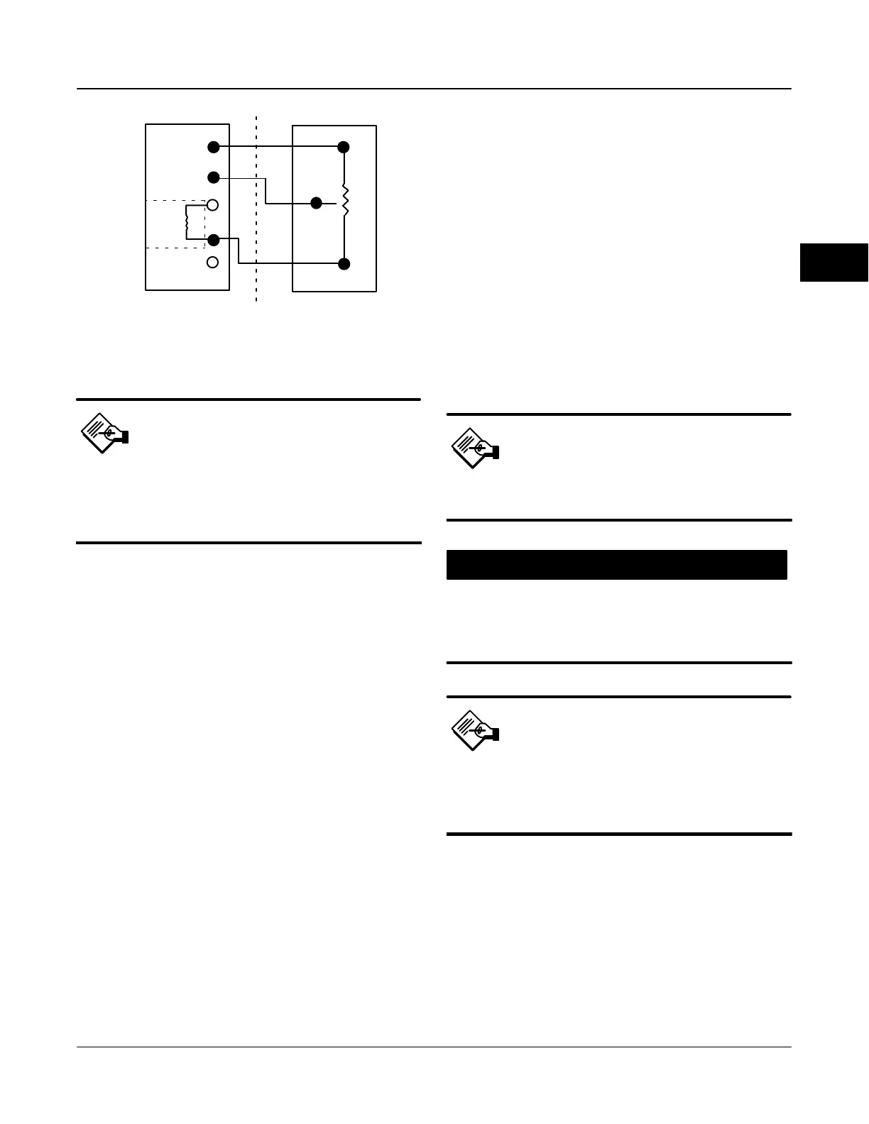
Figure 2-20. Terminal Details for Connecting a DVC6005f
Base Unit and a 10 kOhm External Potentiometer
BASE UNIT TERMINATION BOX
(DVC6005)
3RD PARTY FEEDBACK ELEMENT
(WITH 10k W POTENTIOMETER)
(30k W)
INTERNAL
3
1
30k
2
"
10k W
Note
The digital valve controller must be
configured using the SStem/Roller
selection on the menu of the
appropriate setup device.
The base unit (DVC6005f) was designed to work with
a 40 kOhm potentiometer for travel feedback.
However, there are linear potentiometers that are
readily available with a rated resistance of 10 kOhm.
Therefore, the feedback terminal box on the
DVC6005f contains an additional 30 kOhm fixed
resistor that may be added to the circuit. This brings
the total resistance up to the required 40 kOhm.
1. Stroke the actuator with the 10 kOhm
potentiometer to the mid-travel position, which
corresponds to the potentiometer value of 5 kOhm.
This will leave an equal amount of unused resistive
element on both ends of the travel, which is required
by the digital valve controller to function properly.
2. On the base unit, remove the feedback
connections terminal box cap (refer to figure 2-15).
3. If necessary, install conduit between the
potentiometer and the base unit following applicable
local and national electrical codes. Route the
3-conductor shielded cable between the two units
(refer to figure 2-20).
4. Connect one wire of the 3-conductor shielded cable
between the Terminal labeled “30k Ω” on the base unit
and one end lead of the potentiometer.
5. Connect the second wire of the 3-conductor
shielded cable between the middle lead (wiper) of the
10 kOhm potentiometer and Terminal 2 on the base
unit.
6. Connect the third wire of the 3-conductor shielded
cable between Terminal 3 on the base unit and the
other end-lead of the 10 kOhm potentiometer.
7. Connect the cable shield or drain wire to the
ground screw in the feedback connections terminal
box of the base unit. Do not connect the shield or
drain wire to the external potentiometer.
8. Replace and tighten the base unit cover.
Using a Potentiometer with Two Fixed
Resistors as a Remote Travel Sensor
Perform the following procedures if a potentiometer is
used with the same, or slightly longer travel than the
actuator’s travel.
Note
The potentiometer must be capable of
resistance close to 0 Ohms.
CAUTION
To prevent damage to the
potentiometer, ensure that it is free to
travel the entire length of the actuators
travel.
Note
The digital valve controller must be
configured using the SStem/Roller
selection on the menu of the
appropriate setup device.
This procedure uses three resistors connected in
series; two fixed resistors and one potentiometer.
Three conditions must be met for the resistor
combination to correctly operate the digital valve
controller (refer to figure 2-21):
The maximum resistance of the potentiometer
(R
pot(max)
) must be between 3.9 kOhm and 10 kOhm.
The resistance of R
1
is 4.25 times greater than
R
pot(max)
.
2