2.5 Rotating the transmitter on the sensor
(optional)
For easier access to the user interface or the wiring terminals, the transmitter can be
rotated on the sensor in 45° increments, for eight different orientations.
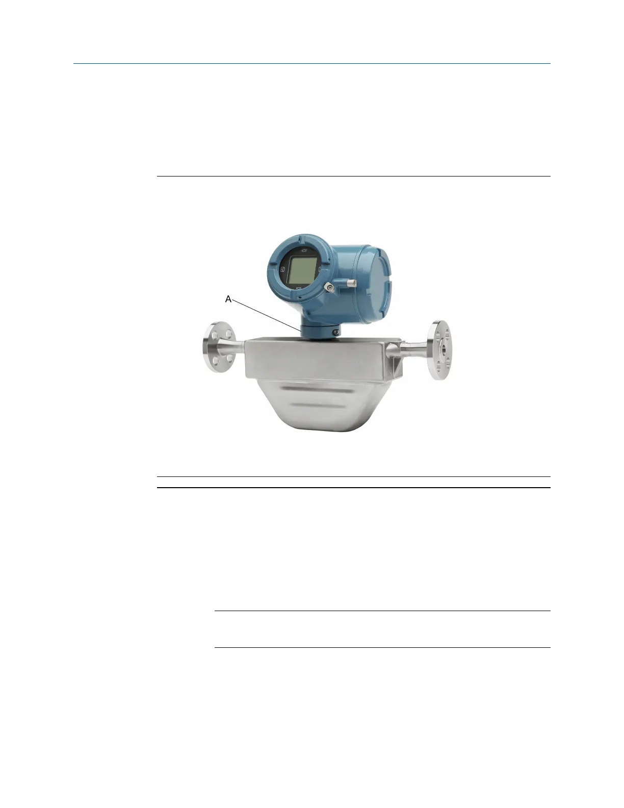
Figure 2-11: Rotating the transmitter on the sensor
A. Clamping ring
Procedure
1. Remove the metal clamping ring from the base of the feed through (refer to Figure
2-11).
2. If the transmitter consists of painted aluminum, do the following:
a) Gently lift the transmitter on the feed through until it disengages from the
notches on the feed through. You will not be able to remove the transmitter
completely.
b) Rotate the transmitter to the desired position.
NOTICE
Do not rotate the housing more than 360°. Excessive rotation can damage the
wiring and cause measurement error or flow meter failure.
c) Lower the transmitter, sliding it onto the notches on the feedthrough.
d) Replace the clamping ring on the feed through. Tighten the screw to 28in lbf
(3.16N m)– 32in lbf (3.62N m).
Installation Manual Mounting and sensor wiring
MMI-20058013 March2024
Installation Manual 19

 Loading...


