3.5 Access the wiring channels
Procedure
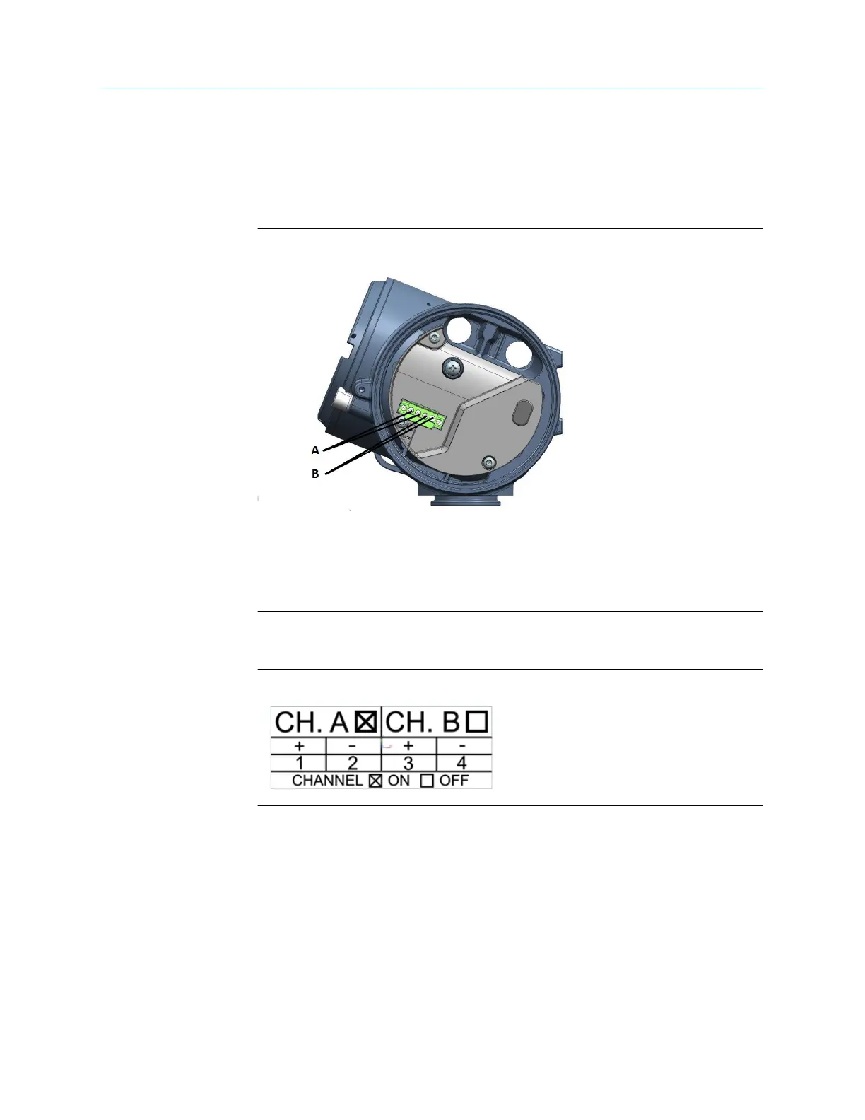
1. Remove the wiring access cover to reveal the I/O wiring terminal block connectors.
Figure 3-5: Channels on the transmitter terminal
A. Channel A connections
B. Channel B connections
2. Confirm which transmitter channels are activated, or ON, and identify the type of
configuration you will be wiring to based on the options available.
Figure 3-6: Activated channel identification
3. (Recommended) Record the channel and wiring configuration on the label provided
inside the transmitter housing cover.
Installation Manual Wiring the channels
MMI-20058013 March2024
Installation Manual 29

 Loading...


