Table 3-1: Barriers verified by Micro Motion
(continued)
Vendor Barrier
Pepperl & Fuchs KFD2-STC1-EX1
Pepperl & Fuchs KFD2-STC4-EX1
MTL 787S+
MTL 7707P+
MTL 7787+
MTL 5042
MTL 3046B
MTL 7728P+
MTL 4541
STAHL 9002/13-280-110-00
PR Electronics 5106
3.4 Channel power requirements
The supply voltage required by the 4200 transmitter depends on the total resistance in the
mA loop. This includes all sense resistance and wire resistance.
Channel A mA HART
®
terminal requirements
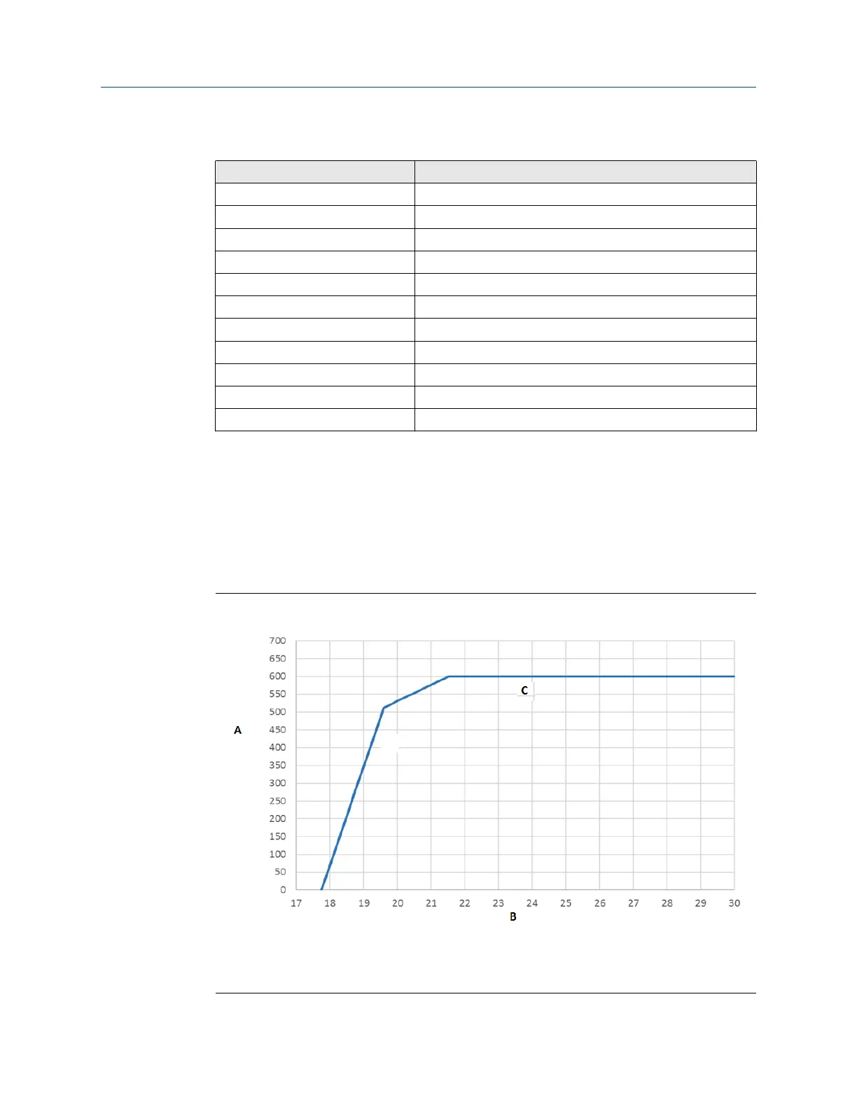
Use the chart below to determine the required supply voltage for Channel A based on loop
resistance.
Figure 3-1: Channel A output supply voltage and loop resistance
A. Loop resistance (Ohms)
B. Supply voltage (Vs)
C. Maximum loop resistance (Ohms)
Installation Manual Wiring the channels
MMI-20058013 March2024
Installation Manual 25

 Loading...


