Safety
Information
Product
information
Mechanical
Installation
Electrical
installation
Getting
started
Basic
parameters
Running
the motor
Optimization
SMARTCARD
operation
Onboard
PLC
Advanced
parameters
Technical
data
Diagnostics
UL
information
Mentor MP User Guide 77
Issue: 3 www.controltechniques.com
7.4 Setting up a feedback device
This section shows more detailed information on parameter settings that must be made to each of the compatible encoder types with Mentor MP. For
more information on the parameters listed here please refer to the Mentor MP Advanced User Guide.
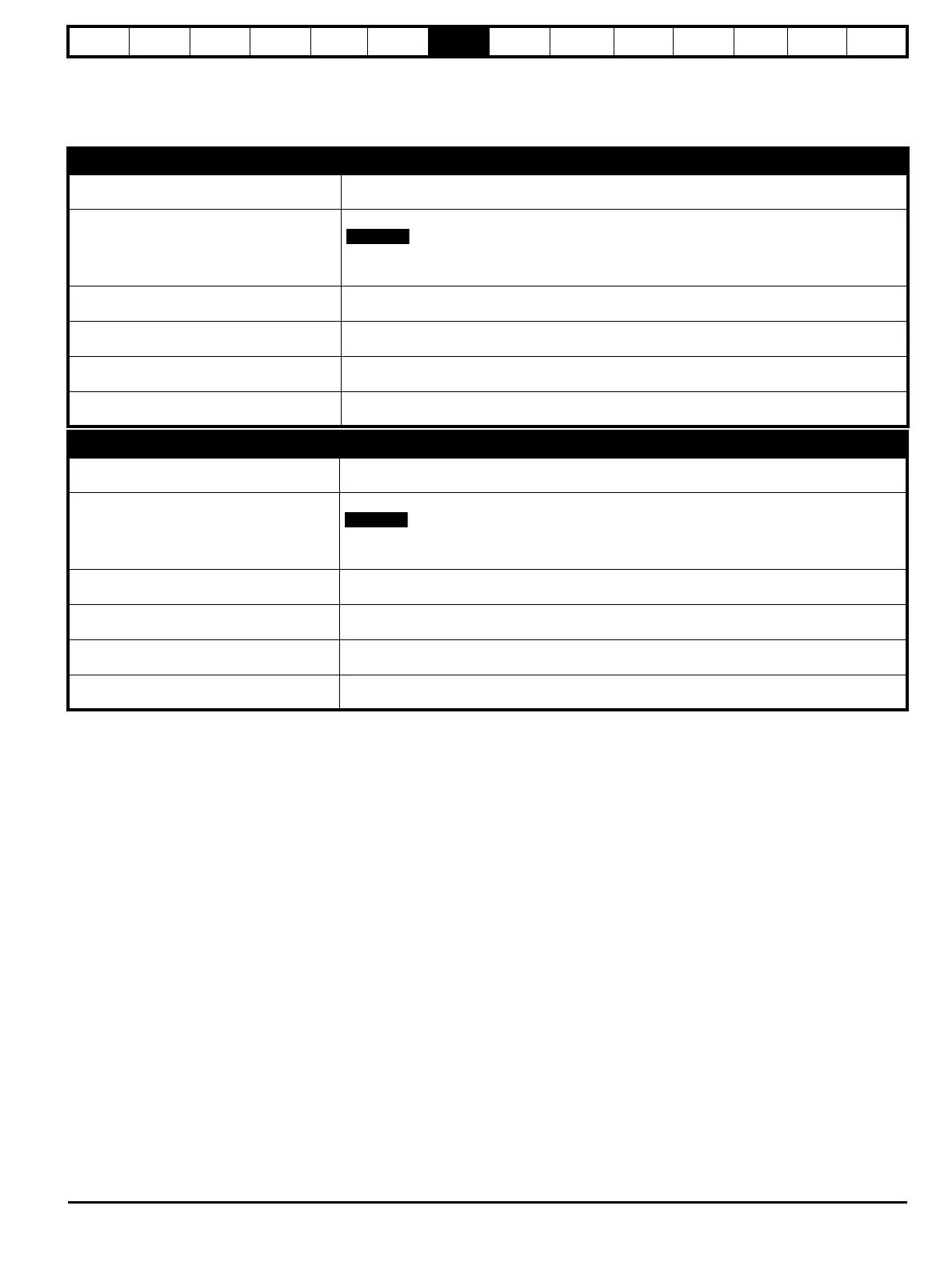
7.4.1 Detailed feedback device commissioning/start-up information
Standard quadrature encoder with or without marker pulse
Encoder type
Pr 3.38
(Fb07, 0.77)
Ab (0) Standard quadrature incremental encoder with or without marker pulse
Encoder power supply voltage
Pr 3.36
(Fb06, 0.76)
5V (0), 8V (1) or 15V (2) or 24V (3)
If the voltage from the encoder is >5V, then the termination resistors must be disabled Pr
3.39
(Fb08, 0.78)
to 0
Encoder number of lines per
revolution
Pr 3.34
(Fb05, 0.75)
Set to the number of lines per revolution of the encoder
Encoder marker mode Pr 3.35
0 = The marker system operates in a conventional manner, 1 = the marker causes a full position
reset.
Encoder termination selection
Pr 3.39
(Fb08, 0.78)
0 = A, B, Z termination resistors disabled, 1 = A, B termination resistors enabled and Z termination
resistors disabled, 2 = A, B, Z termination resistors enabled
Encoder error detection level Pr 3.40
0 = No wire break detect, 1 = Wire break detect on A and B (need termination enabled for 5V
signals), 2 = Wire break detect on A, B and Z (need termination enabled for 5V signals)
Incremental encoder with frequency and direction, or forward reverse signals, with or without marker pulse
Encoder type
Pr 3.38
(Fb07, 0.77)
Fd (2) Incremental encoder with frequency and direction outputs, with or without marker pulse,
Fr (3) Incremental encoder with forward and reverse outputs, with or without marker pulse
Encoder power supply voltage
Pr 3.36
(Fb06, 0.76)
5V (0), 8V (1) or 15V (2) or 24V (3)
If the voltage from the encoder is >5V, then the termination resistors must be disabled Pr
3.39
(Fb08, 0.78)
to 0
Encoder number of lines per
revolution
Pr 3.34
(Fb05, 0.75)
Set to the number of lines per revolution of the encoder divide by 2
Encoder marker mode Pr 3.35
0 = The marker system operates in a conventional manner, 1 = the marker causes a full position
reset.
Encoder termination selection
Pr 3.39
(Fb08, 0.78)
0 = A, B, Z termination resistors disabled, 1 = A, B termination resistors enabled and Z termination
resistors disabled, 2 = A, B, Z termination resistors enabled
Encoder error detection level Pr 3.40
0 = No wire break detect, 1 = Wire break detect on A and B (need termination enabled for 5V
signals), 2 = Wire break detect on A, B and Z (need termination enabled for 5V signals)
 Loading...
