Safety
Information
Product
information
Mechanical
Installation
Electrical
installation
Getting
started
Basic
parameters
Running the
motor
Optimization
SMARTCARD
operation
Onboard
PLC
Advanced
parameters
Technical
data
Diagnostics
UL
information
Mentor MP User Guide 81
Issue: 3 www.controltechniques.com
9 SMARTCARD operation
9.1 Introduction
This is a standard feature that enables simple configuration of
parameters in a variety of ways. The SMARTCARD can be used for:
• Parameter copying between drives
• Saving whole drive parameter sets
• Saving ‘differences from default‘ parameter sets
• Storing Onboard PLC programs
• Automatically saving all user parameter changes for maintenance
purposes
• Loading complete motor map parameters.
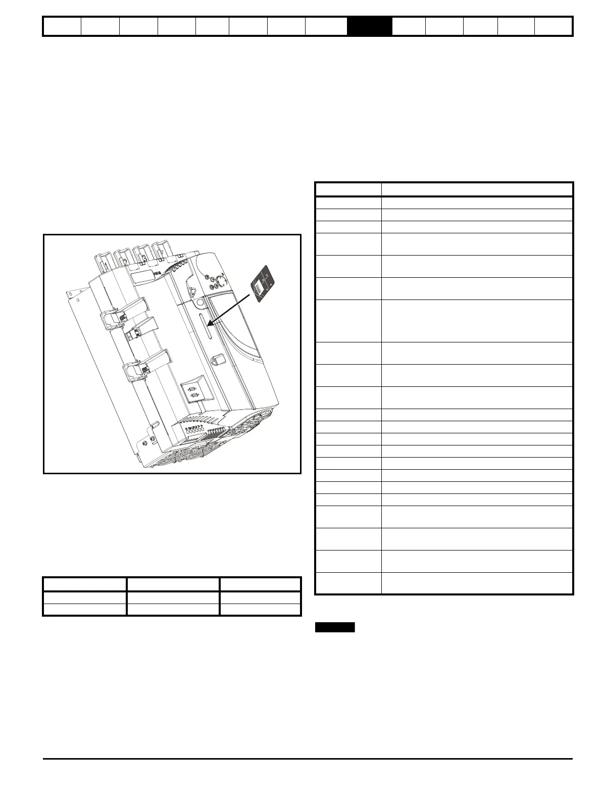
Refer to Figure 9-1 for installing the SMARTCARD. Ensure the
SMARTCARD is inserted with the MP arrow pointing upwards.
The drive only communicates with the SMARTCARD when commanded
to read or write, this means that the card may be ‘hot swapped’.
Figure 9-1 Installation of the SMARTCARD
9.2 Easy saving and reading
The SMARTCARD has 999 individual data block locations. Each
individual location from 1 to 499 can be used to store data.
The drive can support SMARTCARDS that have a capacity of between
4kB and 512kB.
The usage of the data block locations in the SMARTCARD are shown in
Table 9-1.
Table 9-1 SMARTCARD data blocks
Parameter sets labelled as ‘Differences from default‘ will be much
smaller than whole parameter sets. Therefore they use a lot less
memory because most applications only require a few parameters to be
changed from the default setting.
The whole card may be protected from writing or erasing by setting the
read-only flag as shown in section 9.3.9 9888 / 9777 - Set / clear the
SMARTCARD read only flag on page 83.
Either of these indications will tell the user that data is being transferred
to or from the SMARTCARD:
• SM-Keypad: The decimal point after the fourth digit in the upper
display will flash.
• MP-Keypad: The symbol 'CC' will appear in the lower left hand
corner of the display.
The card should not be removed during data transfer because the drive
will trip. If a trip occurs you must either try to transfer the data again or, in
the case of a card-to-drive transfer, the default parameters should be
loaded.
9.3 Transferring data
When a code is entered into Pr xx.00 and the drive is subsequently
reset, the drive will carry out the actions listed in Table 9-2.
Table 9-2 Transferring data
Where yyy indicates the data block number 001 to 999, refer to Table 9-
1 for restrictions on data block numbers.
If the read only flag is set then only codes 6yyy or 9777 are effective.
9.3.1 Writing to the SMARTCARD
3yyy - Transfer data to the SMARTCARD
The data block contains the complete parameter data from the drive, i.e.
all user-save (US) parameters except parameters with the NC coding bit
set. Power-down save (PS) parameters are not transferred to the
SMARTCARD.
Data block Type Example of usage
1 to 499 Read / Write Application set-up
500 to 999 Read Only Macros
P
a
r
a
m
e
t
e
r
-
P
r
0
.
3
0
r
E
A
d
+
A
u
t
o
+
P
r
o
g
+
b
o
o
t
+
Codes Actions
Pr x.00 = rEAd 1 Transfer SMARTCARD data block 1 to the drive.
Pr x.00 = rEAd 2 Transfer SMARTCARD data block 2 to the drive.
Pr x.00 = rEAd 3 Transfer SMARTCARD data block 3 to the drive.
Pr x.00 = PrOg 1
Transfer drive parameters as difference from default
to SMARTCARD data block number 1.
Pr x.00 = PrOg 2
Transfer drive parameters as difference from default
to SMARTCARD data block number 2.
Pr x.00 = PrOg 3
Transfer drive parameters as difference from default
to SMARTCARD data block number 3.
Pr x.00 = 2001
Transfer drive parameters as difference from
defaults to a bootable SMARTCARD data block with
block number 1. This will clear data block 1 on the
card if it already exists.
Pr x.00= 3yyy
Transfer drive parameters to a SMARTCARD data
block number yyy.
Pr x.00 = 4yyy
Transfer drive data as difference from defaults to
SMARTCARD data block number yyy.
Pr x.00= 5yyy
Transfer drive user program to SMARTCARD data
block number yyy.
Pr x.00 = 6yyy Transfer SMARTCARD data block yyy to the drive.
Pr x.00 = 7yyy Erase SMARTCARD data block yyy.
Pr x.00 = 8yyy Compare drive parameters with data block yyy.
Pr x.00 = 9555 Clear SMARTCARD warning suppression flag.
Pr x.00 = 9666 Set SMARTCARD warning suppression flag.
Pr x.00= 9777 Clear SMARTCARD read-only flag.
Pr x.00 = 9888 Set SMARTCARD read-only flag.
Pr x.00 = 9999 Erase SMARTCARD.
Pr 11.42 (SE09,
0.30) = Read
Transfer SMARTCARD data block 1 to the drive
provided it is a parameter file.
Pr 11.42 (SE09,
0.30) = Prog
Transfer drive parameters to a SMARTCARD data
block number 1.
Pr 11.42 (SE09,
0.30) = Auto
Transfer drive parameters to a SMARTCARD data
block with data block number 1 provided.
Pr 11.42 (SE09,
0.30) = boot
Pr 11.42 (SE09, 0.30) has been changed since
power-up.