Safety
Information
Product
information
Mechanical
Installation
Electrical
installation
Getting
started
Basic
parameters
Running the
motor
Optimization
SMARTCARD
operation
Onboard
PLC
Advanced
parameters
Technical
data
Diagnostics
UL
information
Mentor MP User Guide 79
Issue: 3 www.controltechniques.com
When this operation is performed the drive will determine the Motor
constant (Pr 5.15), Continuous proportional gain (Pr 4.13), Continuous
integral gain (Pr 4.14), Discontinuous integral gain (Pr 4.34), Back EMF
set point (Pr 5.59), Armature resistance (Pr 5.60) and Flux loop I gain
(Pr 5.72) with respect to the selected motor map and store the values.
8.4.2 Continuous autotune for current loop gains
In the static autotune the armature current loop gains are set up with no
flux in the motor. In some motors the inductance of the armature
changes significantly when flux is present in the machine. If this is the
case, a continuous autotune can be enabled to correct the gains for the
fluxed machine.
When Pr 5.26 is set to On, the continuous autotune is enabled which
continuously monitors the motor ripple and adjusts Motor constant
(Pr 5.15), Continuous proportional gain (Pr 4.13) and Discontinuous
integral gain (Pr 4.34) for optimum performance.
The static autotune should still be carried out because Continuous
integral gain (Pr 4.14) is not set by the continuous autotune.
Calculation of the gains is suspended when the voltage spill over loop
becomes active so that the gains are not increased when the field is
weakened (less flux in the machine).
This function does not operate when the drives are set-up in serial 12
pulse.
8.4.3 Drive commissioning output
The Mentor MP has a test pin that gives instantaneous armature current
feedback. The pin is identified by a half sign wave symbol and is located
to the right of the tachometer terminals. An oscilloscope probe can be
attached to this pin to monitor the armature current.
8.5 Speed loop gains tuning
The speed loop gains control the response of the speed controller to a
change in speed demand. The speed controller includes proportional
(Kp) and integral (Ki) feed forward terms, and a differential (Kd)
feedback term. The drive holds two sets of these gains and either set
may be selected for use by the speed controller with Pr 3.16
Pr 3.16 may be changed when the drive is enabled or disabled.
• If Pr 3.16 = 0 - gains Kp1, Ki1 and Kd1 are used
• If Pr 3.16 = 1 - gains Kp2, Ki2 and Kd2 are used
8.5.1 Proportional gain (Kp) Pr 3.10 (SP01, 0.61) and
Pr 3.13
If Kp has a value and the integral gain Ki is set to zero the controller will
only have a proportional term, and there must be a speed error to
produce a torque reference. Therefore as the motor load increases there
will be a difference between the reference and actual speeds.
This effect, called regulation, depends on the level of the proportional
gain, the higher the gain the smaller the speed error for a given load.
If the proportional gain is too high either the acoustic noise produced by
speed feedback quantization becomes unacceptable, or the stability limit
is reached.
8.5.2 Integral gain (Ki) Pr 3.11 (SP02, 0.62) and
Pr 3.14
The integral gain is provided to prevent speed regulation. The error is
accumulated over a period of time and used to produce the necessary
torque demand without any speed error. Increasing the integral gain
reduces the time taken for the speed to reach the correct level and
increases the stiffness of the system, i.e. it reduces the positional
displacement produced by applying a load torque to the motor.
Unfortunately increasing the integral gain also reduces the system
damping giving overshoot after a transient. For a given integral gain the
damping can be improved by increasing the proportional gain. A
compromise must be reached where the system response, stiffness and
damping are all adequate for the application. The term is implemented in
the form of
Σ(Ki x error), and so the integral gain can be changed when
the controller is active without causing large torque demand transients.
8.5.3 Differential gain (Kd) Pr 3.12 (SP03, 0.63) and
Pr 3.15
The differential gain is provided in the feedback of the speed controller to
give additional damping. The differential term is implemented in a way
that does not introduce excessive noise normally associated with this
type of function. Increasing the differential term reduces the overshoot
produced by under-damping, however, for most applications the
proportional and integral gains alone are sufficient.
8.5.4 Manually setting up the speed loop gains
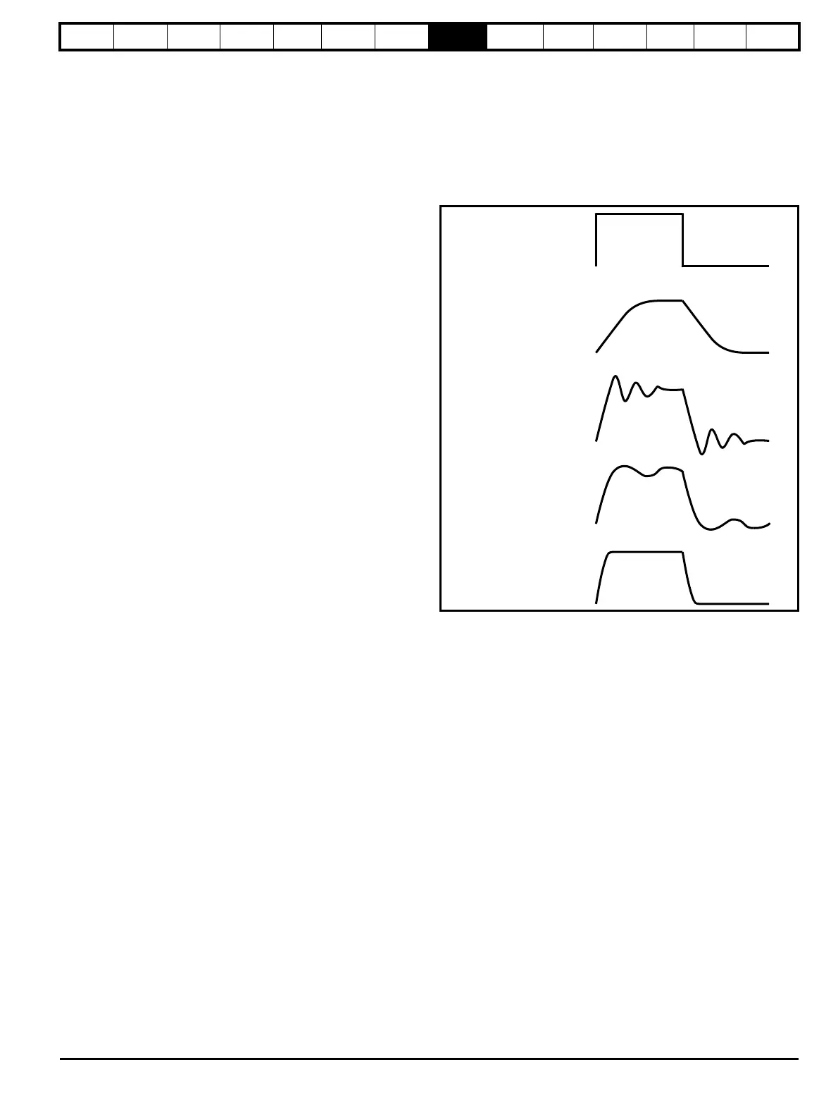
Figure 8-1 Responses
There are two methods of tuning the speed loop gains dependant on the
setting of Pr 3.17:
1. Pr 3.17 = 0, User set-up.
This involves the connecting of an oscilloscope to analog output 1 to
monitor the speed feedback. Give the drive a step change in speed
reference and monitor the response of the drive on the oscilloscope.
The proportional gain (Kp) should be set up initially. The value should be
increased up to the point where the speed overshoots and then reduced
slightly.
The integral gain (Ki) should then be increased up to the point where the
speed becomes unstable and then reduced slightly.
It may now be possible to increase the proportional gain to a higher
value and the process should be repeated until the system response
matches the ideal response as shown.
Figure 8-1 shows the effect of incorrect P and I gain settings as well as
the ideal response.
2. Pr 3.17 = 1, Bandwidth set-up
If bandwidth based set-up is required, the drive can calculate Kp and Ki
if the following parameters are set up correctly:
Pr 3.18 - Motor and load inertia - it is possible to measure the load inertia
as part of the auto-tuning process (see Pr 5.12 (SE13, 0.34)).
Pr 3.20 - Required bandwidth,
Pr 3.21 - Required damping factor,
Pr 5.32 - Motor torque per amp (Kt).
proportional
gain
Excessive proportional
gain
Excessive integral gain
Ideal response
 Loading...
