ER5000 —
106
Installation Variations
Wiring Variations for Additional Functions
Monitoring the ER5000’s Internal Sensor Using the
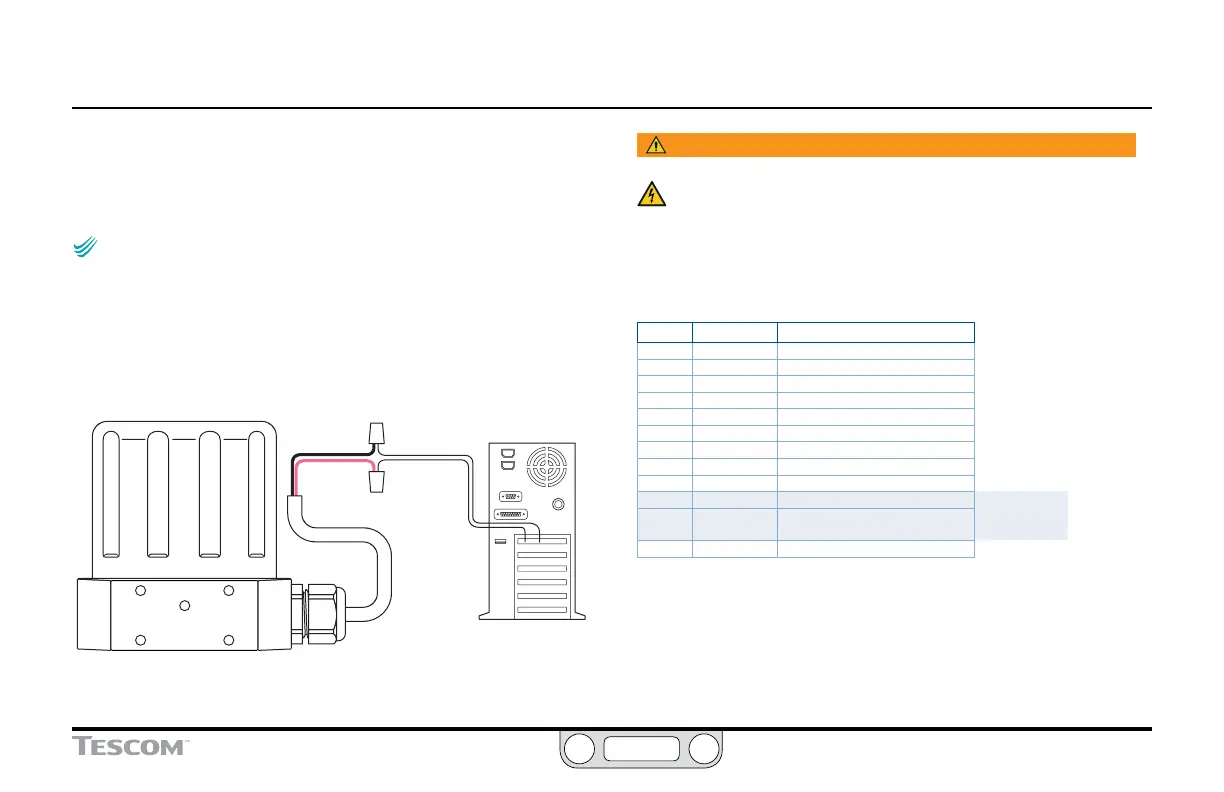
Analog Output, 0–10V Wiring
NOTENOTE
CAUTIONCAUTION
WARNINGWARNING
This feature is only available on “F” models of the ER5000.
The ER5000 provides the capability of monitoring the internal
sensor through direct wiring to the PC. The internal sensor
can, alternatively, be monitored through the USB or RS485
connection between the ER5000 and the PC by reading
variable #6 (ID_COMPENSATED_INTERNAL_SENSOR).
BLACK
PINK
- V IN
+V IN
PC
Figure 41: Monitor Internal Sensor (0–10V Wiring)
WARNING
The controller must be disconnected from the power supply before
any additional wiring or change to jumper configuration is
performed. Do not reconnect the power supply until all additional
wiring connections have been made and are properly installed.
Refer to Table 24 to verify correct wiring.
Table 24: Wiring for Monitoring Internal Sensor (0–10V)
J3 Pins Wire Color Function
1 brown +setpoint input
2 red -setpoint input
3 orange +feedback input
4 yellow -feedback input
5 green -RS485 network connection
6 blue +RS485 network connection
7 violet +24V DC power
8 gray 24V return (power ground)
9 white +5V output (5 mA max.)
10 black analog signal/board ground
*11 *pink analog signal output
(active in Enhanced “F” models ONLY)
12 tan analog signal/board ground

 Loading...

