ER5000 —
62
Getting Started
2
Verify the configuration of your application
WARNING
Improper selection of controllers, regulators, valves or accessories
can cause death, serious injury and/or property damage.
WARNING
Installation in a hazardous location requires additional steps not
described in this section. Refer to Installing a Hazardous Location
Model (ER5050) on page 110 for more information.
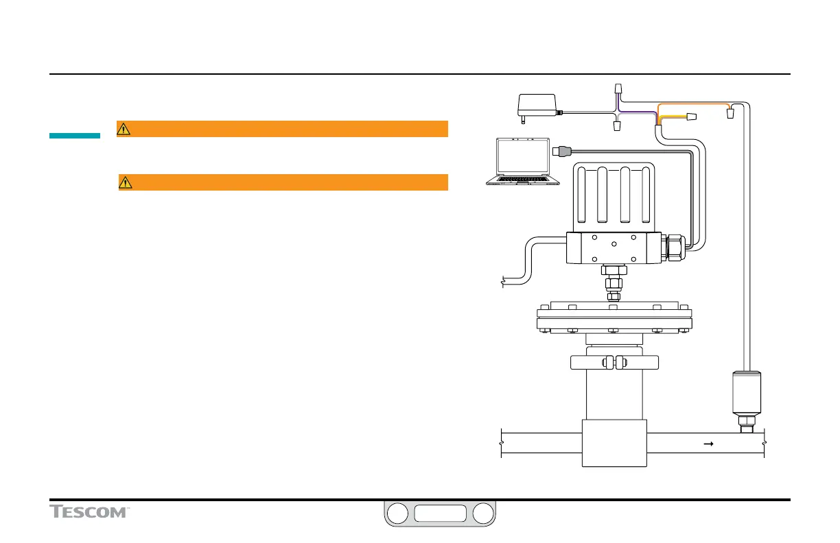
This section assumes you will be installing the ER5000
in a typical configuration, which is shown in Figure 7 and
includes the following components and connections:
• ER5000SI-1
• Controller is mounted on top of an air actuated pressure
reducing regulator
• 1/2" SAE x 1/8" NPTF adaptor is used to connect
controller to regulator
• External Feedback control mode
• Feedback source is a two-wire 4–20 mA transducer
• Controller is connected to a PC which is running the
ERTune™ program, connected via USB using the Mini-B USB
port on the ER5000’s control board
For information on other applications and alternative wiring
congurations, refer to the Installation Variations section.
ER5000 Supply
Pressure
110 psig / 7.5 bar
Transducer
USB Connection
Power
Supply
+24V DC
VIOLET
YELLOW
ORANGE
+ SUPPLY
+ SUPPLY
+ OUTPUT
GRAY
TAN
PC
Supply Pressure
To Process
Regulator
GROUND
Adaptor
Figure 7: Typical Application Setup of the ER5000

 Loading...

